Eureka AIR delivers breakthrough ideas for toughest innovation challenges, trusted by R&D personnel around the world.

Hydraulic system of construction machine

A hydraulic system and construction machinery technology, applied in the field of hydraulic systems, can solve problems such as the decrease in engine speed, achieve the effects of preventing hydraulic shock, improving fuel efficiency, and preventing a sharp drop in engine speed

Active Publication Date: 2014-08-27
HYUNDAI DOOSAN INVIGORATE CORP
View PDF5 Cites 10 Cited by
  • Summary
  • Abstract
  • Description
  • Claims
  • Application Information

AI Technical Summary

Problems solved by technology

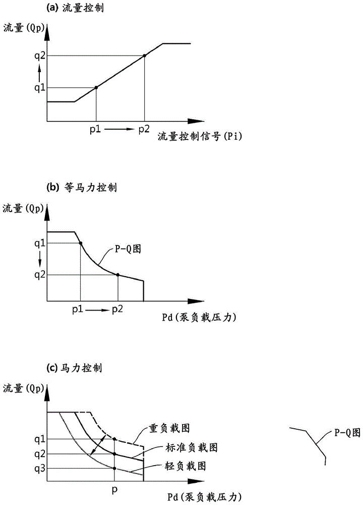
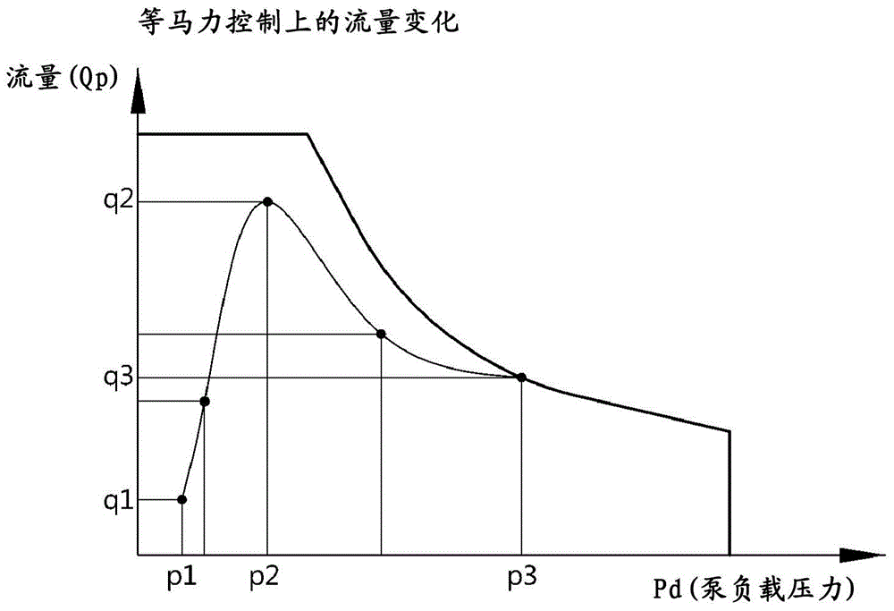
[0044] However, in terms of horsepower control, there is no flow control method that can reduce the discharge flow rate determined by the joystick or the travel lever, so there is a problem that the engine speed (rpm) drops when the initial start or sudden start is operated.

Method used


Image

  • Hydraulic system of construction machine
  • Hydraulic system of construction machine
  • Hydraulic system of construction machine

Examples


Embodiment Construction

[0070] Advantages and features of the present invention and methods for achieving them will be clarified with reference to the accompanying drawings and the following embodiments described in detail.

[0071] Throughout the specification, the same reference numerals refer to the same constituent elements, and the same constituent elements as those in the prior art are given the same numerals and repeated explanation thereof will be omitted.

[0072] On the other hand, the following terms are set in consideration of the functions in the present invention, and may vary depending on the manufacturer's intention or customary practice. Therefore, these terms should be defined based on the entire contents of this specification. definition.

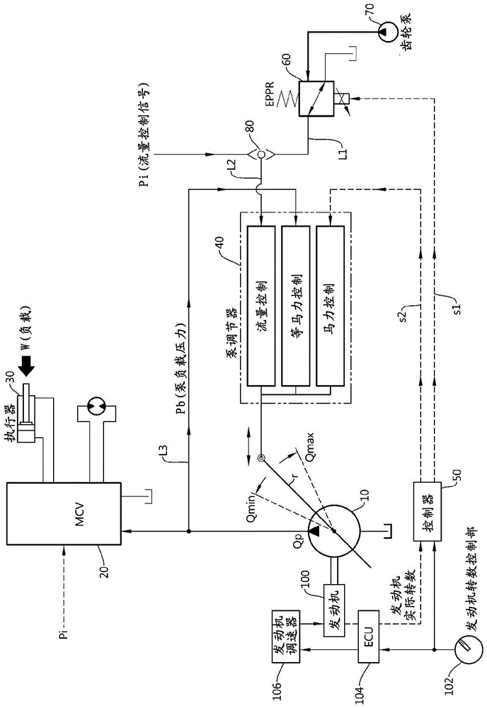
[0073] Refer below Figure 5 , the hydraulic system of the construction machine according to one embodiment of the present invention will be described.

[0074] Attached picture Figure 5 It is a figure for explaining the hydraulic system of ...


PUM


Abstract

The present invention relates to a hydraulic system of a construction machine. A hydraulic system of a construction machine according to the present invention includes: an EPPRV (60, Electronic Proportional Pressure Reducing Valve) for controlling a flow rate, to which maximum pressure is input as a control current value and which is set to a minimum flow rate; a gear pump (70) for providing pilot operation oil to the EPPRV (60); a shuttle valve (80) for comparing the pressure of first pilot operation oil which has passed through the EPPRV (60) and the pressure of a flow rate control signal and then outputting second pilot operation oil of greater pressure; a hydraulic pump (10) of which swash plate angle is controlled by the second pilot operation oil; and a pump control device (50) for controlling the pressure of the EPPRV (60) to be reduced from the maximum pressure according to a set inclination if the flow rate control signal is generated.

Description

technical field [0001] The present invention relates to a hydraulic system of a construction machine, and more specifically, to a hydraulic system of a construction machine equipped with a mechanical hydraulic pump, which reduces excessive fuel consumption and improves fuel efficiency when an operator operates a joystick in a hurry And the hydraulic system of operational engineering machinery. Background technique [0002] Generally speaking, in a hydraulic system, hydraulic fluid is discharged from the system hydraulic pump, and the hydraulic fluid waits at the inlet of the main control valve. Multiple spools are provided inside the main control valve, and multiple actuators are connected to the outside. In addition, pilot pressure is generated as a flow control signal in flow rate requesting units such as joysticks and pedals, and the pilot pressure is supplied to the main control valve. The main control valve opens and closes a specific spool according to the pilot pres...

Claims


Application Information

Patent Timeline
Patent Type & Authority Applications(China)
IPC IPC(8): F15B13/02F15B13/043F15B13/044F15B21/08
CPCF15B13/0426E02F9/2285E02F9/2292E02F9/2235E02F9/2296F15B11/0423F15B11/17F15B2211/20523F15B2211/20553F15B2211/20576F15B2211/3052F15B2211/50554F15B2211/513F15B2211/526F15B2211/633F15B2211/6355F15B2211/6652F15B2211/6654F15B2211/6655F15B2211/6658F15B2211/7142F15B2211/8606F15B2211/8613F16K47/00F15B13/0433F15B13/028E02F9/2267B60Y2200/41F15B11/167F15B11/165
Inventor 房在锡
Owner HYUNDAI DOOSAN INVIGORATE CORP
Why Eureka
Eureka Blog
Learn More