
Embedded type penstock backfill grouting structure and grouting technology

A pressure steel pipe, backfill grouting technology, applied in water conservancy projects, hydropower, hydropower stations, etc., can solve the problems of long construction period, large blindness, complicated process, etc., and achieve the effect of shortening the construction period and solving the void

Active Publication Date: 2014-09-03
CHINA POWER CONSRTUCTION GRP GUIYANG SURVEY & DESIGN INST CO LTD
View PDF4 Cites 4 Cited by
  • Summary
  • Abstract
  • Description
  • Claims
  • Application Information

AI Technical Summary

Problems solved by technology

At present, the backfill grouting treatment methods mainly include reserved holes in the steel pipe roof arch or pre-buried grouting pipes along the rock wall. The reserved hole method has a large number of openings, large blindness, and the hole diameter is usually greater than 50mm. The welding reinforcement process requires high requirements. And there is a safety hazard of internal water leakage due to leakage welding. The pre-embedded pipe method is easy to be blocked during construction and affects the grouting effect in the later stage, and the construction period is long, the process is complicated, the blindness is large, the project investment is large, and the safety and reliability are poor.

Method used


Image

  • Embedded type penstock backfill grouting structure and grouting technology
  • Embedded type penstock backfill grouting structure and grouting technology
  • Embedded type penstock backfill grouting structure and grouting technology

Examples


Embodiment Construction

[0027] The technical solution of the present invention is further described below in conjunction with the accompanying drawings, but the scope of protection is not limited to the description.

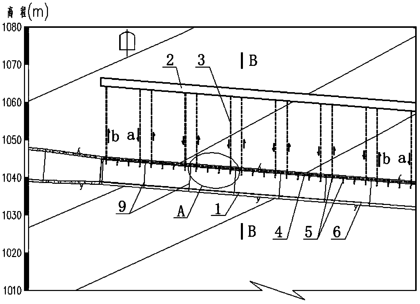
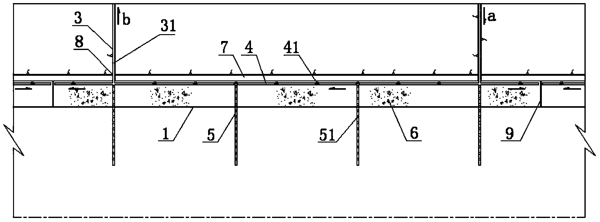
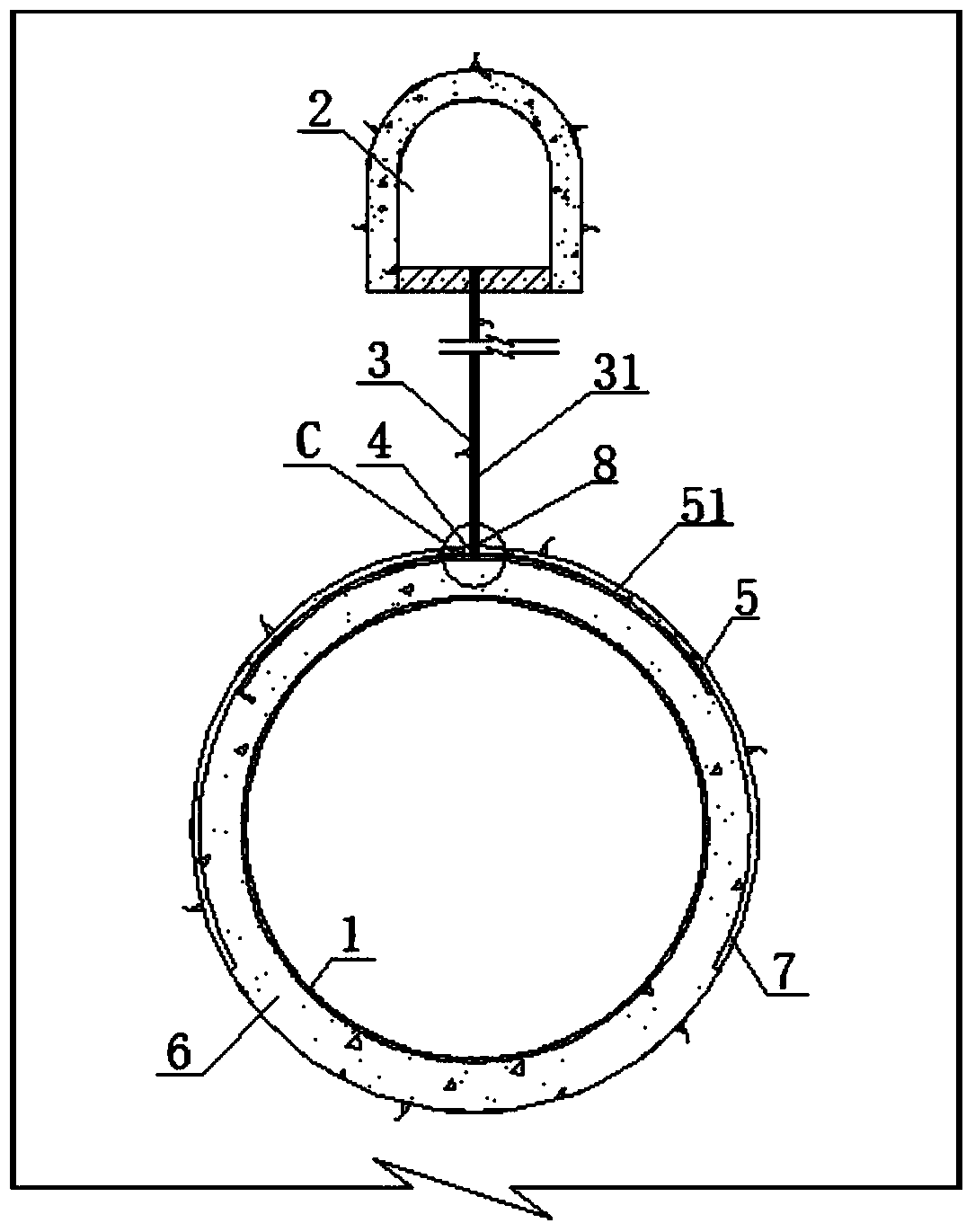
[0028] Such as Figure 1 to Figure 4 As shown, a buried penstock backfill grouting structure according to the present invention includes a penstock 1 and a drainage hole 2 arranged outside the penstock 1, and the outside of the penstock 1 is pre-embedded with a number of longitudinal grouting through the backfill concrete 6 The pipe 4 and the transverse grouting pipe 5 are provided with shotcrete 7 on the outer surface of the backfill concrete 6, the drainage hole 2 is provided with a rock hole 3, and a grouting pipe 31 is embedded in the rock hole 3, and the grouting pipe 31 is respectively It communicates with the longitudinal grouting pipe 4 and the transverse grouting pipe 5 .

[0029] The diameter of the rock hole 3 is 75mm.

[0030] The top of the longitudinal grouting pipe 4 is...


PUM


Abstract

The invention discloses an embedded type penstock backfill grouting structure and a grouting technology. The grouting structure comprises a penstock and a water draining opening formed in the outside the penstock, wherein a plurality of longitudinal grouting pipes and a plurality of transverse grouting pipes are embedded in the outer side of the penstock through backfill concrete, pneumatically placed concrete is arranged on the outer surface of the backfill concrete, the water draining opening is provided with rock holes in which grouting pipes are embedded, and the grouting pipes are communicated with the longitudinal grouting pipes and the transverse grouting pipes. The grouting technology comprises the steps of drilling, pipe embedding, grouting, grouting completing, hole sealing and quality checking. The grouting structure is arranged in cooperation with the water draining opening, the grouting pipes embedded in the rock holes are communicated with the grouting pipes embedded outside the penstock, grouting is performed by adopting the pushing grouting method, so that the penstock and surrounding rock bear force in a linkage mode, it is guaranteed that pressure of internal water is transmitted fully, whole stress of the penstock, the concrete and the surrounding rock is guaranteed, and the problem of the void between the backfill concrete and the surrounding rock is solved.

Description

technical field [0001] The invention relates to a buried pressure steel pipe backfill grouting structure and a grouting process thereof, belonging to the technical field of water conservancy and hydropower. Background technique [0002] The pressure pipeline of a hydropower station refers to the pipeline that transports water from the reservoir, the forebay or the surge chamber to the turbine in the power plant. The buried pressure steel pipe refers to the steel pipe that is buried in the rock body and filled with concrete between the steel pipe and the surrounding rock. According to the development of hydropower engineering construction, due to factors such as penstock structure layout, uneven excavation surface, concrete shrinkage or improper construction technology in most projects, penstocks with slopes slower than 45° are backfilled between the top arch of the concrete liner and the surrounding rock. When there is a large "void" that affects the safety of the steel pipe...

Claims


Application Information

Patent Timeline
Patent Type & Authority Applications(China)
IPC IPC(8): E02B9/06
CPCY02E10/22Y02E10/20
Inventor 湛正刚申显柱罗玉霞李晓彬孙卫杜帅群任兴普
Owner CHINA POWER CONSRTUCTION GRP GUIYANG SURVEY & DESIGN INST CO LTD
Learn More