Double-shaft air-injection rotary jet type stirring pile machine and method for forming pile by using pile machine

A technology of mixing pile machines and mixers, which is applied to sheet pile walls, buildings, and foundation structure engineering, etc., which can solve the problems of high mechanical and labor costs, reduced pile quality, unevenness, etc., and save mechanical shifts Cost and labor costs, avoiding insufficient slurry volume, and the effect of uniform and compact cement soil

Active Publication Date: 2014-09-03
NINGBO HONGCHEN CONSTR +1
View PDF6 Cites 14 Cited by
  • Summary
  • Abstract
  • Description
  • Claims
  • Application Information

AI Technical Summary

Problems solved by technology

[0005] There is a big defect in the traditional pile driver and the method of using the traditional pile driver to form a pile, that is, the fluidity of the cement slurry in the soil is poor, and it is difficult to spread evenly, so that a large amount of cement slurry accumulates near the spray nozzle, and the slurry at a slightly farther position The quantity is seriously insufficient, and the grout nozzle is easily blocked by crushed soil, which naturally leads to the lack of cement slurry in the soil, so after stirring, the cement soil of the pile body is not dense and uneven, which seriously reduces the quality of the pile; moreover, as the soil layer As the depth increases, the hardness of the soil increases, and the slurry is diffic

Method used


Image

  • Double-shaft air-injection rotary jet type stirring pile machine and method for forming pile by using pile machine
  • Double-shaft air-injection rotary jet type stirring pile machine and method for forming pile by using pile machine

Examples


Embodiment Construction

[0019] The present invention will be further described below in conjunction with the accompanying drawings and specific embodiments.

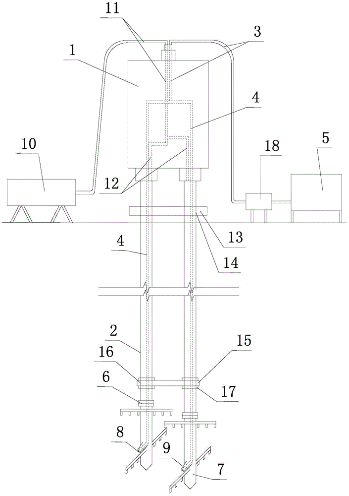
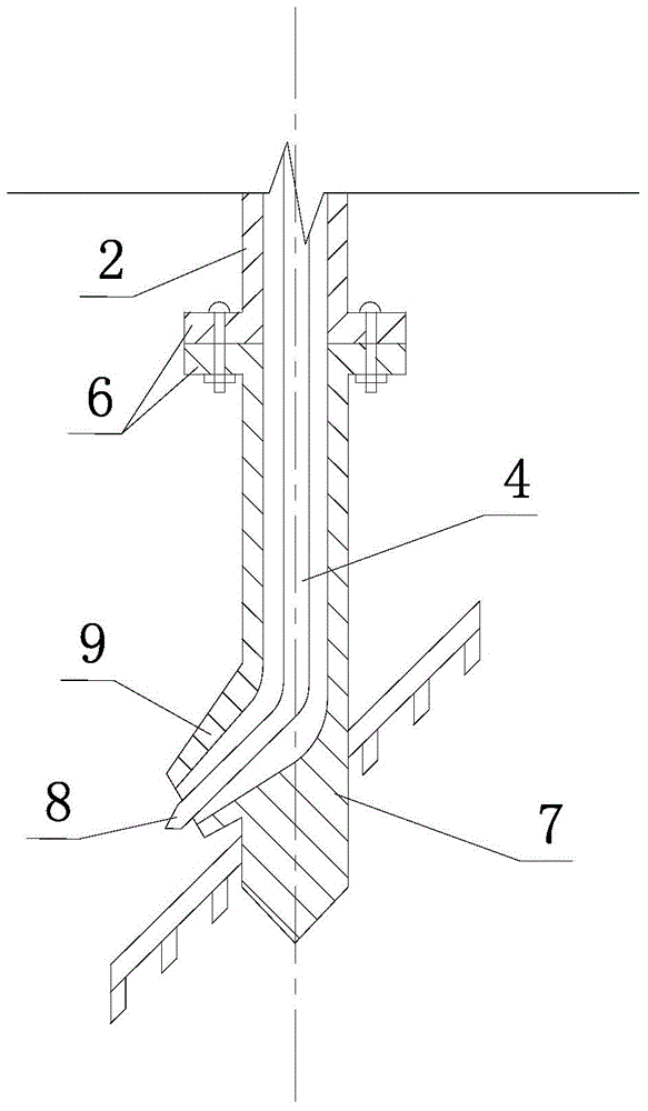
[0020] Such as figure 1 , figure 2 As shown, the biaxial pressure cyclone-jet mixing pile driver of the present invention includes a pile frame, a power head 1, two parallel stirring shafts 2, a main slurry delivery pipe 3, two slurry delivery sub-pipes 4, and a slurry delivery pump 18 and slurry mixer5. The power head 1 is installed on the pile frame, the stirring shaft 2 is hollow tubular and the two stirring shafts 2 are installed at the lower end of the power head 1, and the lower end of each stirring shaft 2 is fixed with a stirring head 7 with a stirring blade through a flange 6 . Each mixing head 7 is fixed with a spray nozzle 8, and each spray nozzle 8 communicates with the slurry pump 18 through the slurry delivery branch pipe 4 and the slurry delivery main pipe 3, and the slurry delivery pump 18 communicates with the slurry mixer ...


PUM


Abstract

The invention discloses a double-shaft air-injection rotary jet type stirring pile machine and a method for forming a pile by using the pile machine. The pile machine disclosed by the invention comprises a pile frame, a power head (1), a stirring shaft (2), an air nozzle (9), an air compressor (10), an air transmission header pipe (11) and an air transmission branched pipe (12); a slurry nozzle (8) and the air nozzle (9) are fixed on a stirring head (7); the air nozzle (9) is arranged outside the slurry nozzle (8) in a sleeving manner; the air nozzle (9) is communicated with the air transmission branched pipe (12); the air transmission branched pipe (12) is communicated with the air transmission header pipe (11) and the air compressor (10). The construction method provided by the invention comprise the key step of spraying slurry under coercing of high-pressure air while drilling through a stirring shaft (2) or lifting upwardly and stirring a soil body. Due to the pile machine and the method for forming the pile by utilizing the pile machine, which are disclosed by the invention, piled cemented soil is uniform in density and good in pile-forming quality; the pile-forming depth can be increased; furthermore, a pile can be formed in a soil body with relatively high hardness; in addition, the construction efficiency is improved; the time limit for a project is shortened; the machine-shift cost and the labour cost are saved.

Description

technical field [0001] The invention relates to the construction technology of cement mixing piles in the field of civil engineering, in particular to a biaxial pressure cyclone jet mixing pile driver and a method for forming piles by using the pile driver. Background technique [0002] With the rapid development of the country's economic construction, especially the widespread rise of housing construction and municipal construction, the construction technology of cement mixing piles is also constantly being developed and applied. Cement mixing piles are mostly used for foundation reinforcement or as support structures and water-stop curtains in foundation pit support systems. [0003] The traditional cement mixing pile machine includes a pile frame, a power head, two parallel stirring shafts (that is, double stirring shafts), a main slurry delivery pipe, two slurry delivery sub-pipes, a slurry delivery pump and a slurry mixer. The power head is installed on the pile On the...

Claims


Application Information

Patent Timeline
IPC IPC(8): E02D5/46
Inventor 李福连陶灵聪陈勇李杰
Owner NINGBO HONGCHEN CONSTR
Why Eureka
Try Eureka