
Measurement device and method for fracture shapes after physical model samples are fractured

A crack shape and measuring device technology, applied in the field of petroleum industry, can solve problems such as complex operation, difficult operation, complex equipment, etc., and achieve the effect of accurate identification, convenient use and simple operation

Active Publication Date: 2014-09-03
CHINA UNIV OF PETROLEUM (BEIJING)
View PDF7 Cites 8 Cited by
  • Summary
  • Abstract
  • Description
  • Claims
  • Application Information

AI Technical Summary

Problems solved by technology

In terms of visual observation, the distribution range of the tracer can be observed by the labeling of the tracer, but the fracture shape cannot be characterized; the sample is processed with a transparent material, which is limited to the large difference between the mechanical properties of the transparent material and the rock; based on the solidification fluid As a fracturing fluid, the material is cured in the fracture to realize the visualization of the fracture, which is affected by the temperature and the difficulty of separation after curing
In terms of indirect monitoring, the acoustic emission monitoring method can detect crack expansion in real time, but the effective identification of acoustic emission signal points is very difficult, and the simulation results are not intuitive enough; ultrasonic testing, CT scanning, and infrared thermal imaging have the advantages of high equipment sensitivity and detection The result is intuitive, but there are problems such as difficulty in identifying multiple cracks, high cost, and difficult operation
[0003] The Chinese invention patent with the application number 201210287011.3 discloses a hydraulic fracturing fracture monitoring device and monitoring method based on electrokinetic coupling. The device consists of three parts: a front-end conditioning module, a data acquisition module and a main control module. The problem that the monitoring results exceed the actual fracture size is high cost, complex equipment, difficult operation, and difficult identification of multiple fractures, which is not suitable for indoor hydraulic fracturing physical experiment simulation
The Chinese invention patent with the application number 201310019575.3 discloses a spatial reconstruction method of formation fractures based on core measurement. This method is difficult to identify multiple fractures, the operation is complicated, and it is not suitable for indoor hydraulic fracturing physical experiment simulation.

Method used


Image

  • Measurement device and method for fracture shapes after physical model samples are fractured
  • Measurement device and method for fracture shapes after physical model samples are fractured
  • Measurement device and method for fracture shapes after physical model samples are fractured

Examples


Embodiment 1

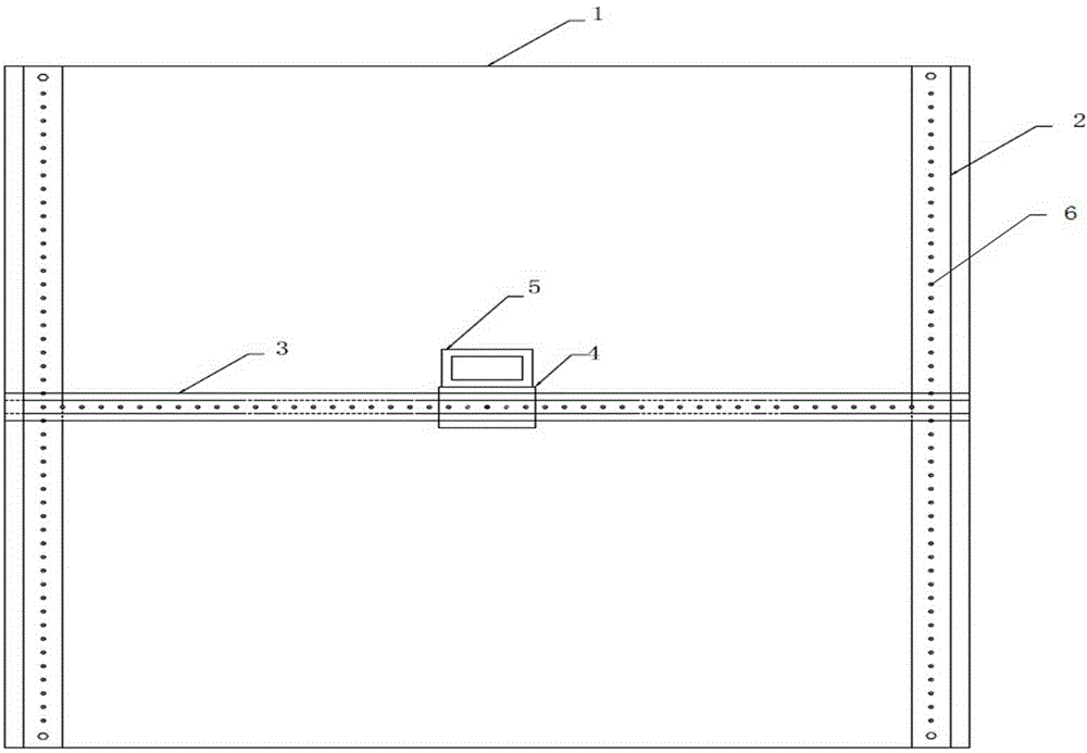
[0049] A device for measuring the fracture shape of a physical model sample after fracturing, such as figure 1 As shown, it comprises a test frame 1, a positioning clamp 2 is installed on the test frame 1, a linear positioning guide rail 3 is installed on the positioning clamp 2, and a positioning slide block 4 is connected on the linear positioning guide rail 3. The positioning slider 4 is fixed together with the positioning box 5, and a laser rangefinder is housed in the positioning box 5, and the positioning slider 4 can drive the positioning box to move laterally on the linear positioning guide rail. The positioning guide rail can move longitudinally on the positioning clip.

[0050] In this embodiment, the positioning clip 2 is fixed on the test frame 1 by bolts, and the linear positioning guide rail 3 is fixed on the positioning clip 2 by positioning pins, and can be positioned on the positioning clip 2. Move vertically.

[0051] In this embodiment, the positioning sli...

Embodiment 2

[0076] A device for measuring the shape of cracks after fracturing of a physical model sample, which includes a test frame 1, a positioning clip 2 is installed on the test frame 1, and a linear positioning guide rail 3 is installed on the positioning clip 2. The linear positioning guide rail 3 is connected with a positioning slider 4, the positioning slider 4 is fixed with the positioning box 5, a laser rangefinder is housed in the positioning box 5, and the positioning slider 4 can drive the positioning The box moves laterally on the linear positioning guide rail, and the positioning guide rail can move longitudinally on the positioning clip bar.

[0077] In this embodiment, the positioning clip 2 is fixed on the test frame 1 by welding, and the linear positioning guide rail 3 is fixed on the positioning clip 2 through positioning pins, and can be positioned on the positioning clip 2. Move vertically.

[0078] In this embodiment, the positioning slide block 4 can slide freel...

Embodiment 3

[0103] A kind of method for measuring the fracture shape after the fracturing of the physical model sample, the device used is the measuring device in embodiment 1, this method is basically the same as that of embodiment 1, and the difference is to include the following steps:

[0104] A, carry out fracturing test to rock core sample, after described rock sample is fractured to produce crack, stop injecting fracturing fluid;

[0105] B, the rock core sample in the step A is opened along the fracture surface of each depressing, be placed on above-mentioned test frame 1 of the measuring device of the fracture form after the fracturing of the physical model sample;

[0106] C. Move the linear positioning guide rail 3 longitudinally along the positioning clip 2, the linear positioning guide rail 3 drives the positioning slider 4 to move, and the positioning slider 4 drives the positioning box 5 to move together, thereby realizing the longitudinal movement of the laser rangefinder ...


PUM


Abstract

The invention belongs to the technical field of the oil industry, and particularly relates to a measurement device and method for fracture shapes after physical model samples are fractured. The device comprises a test rack (1), locating clamping strips (2) are installed on the test rack (1) and are provided with a linear locating guide rail (3), the linear locating guide rail (3) is connected with a locating sliding block (4), the locating sliding block (4) and a locating box (5) are fixed together, a laser distance measuring instrument is installed in the locating box (5), the locating sliding block (4) can drive the locating box (5) to transversely move on the linear locating guide rail (3), and the linear locating guide rail (3) can longitudinally move on the locating clamping strips (2). The device is easy to operate, low in cost, convenient to use and high in precision, and the measurement method for the fracture shapes after the physical model samples are fractured through the device is applicable to indoor hydraulic fracturing physical experiment simulation and can accurately recognize multiple fractures.

Description

technical field [0001] The invention belongs to the technical field of the petroleum industry, and in particular relates to a measuring device and method for a fracture shape of a physical model sample after fracturing. Background technique [0002] The geometry of hydraulic fractures is one of the main factors affecting the effect of fracturing treatment. The monitoring and identification of fracturing fractures is a difficult point in fracturing design, especially in shale gas reservoirs that need to be stimulated through horizontal well drilling and multi-stage fracturing technology, and the formation of natural fractures in the reservoir after fracturing will be complicated The network fractures bring more challenges to the monitoring of fracture propagation patterns. The indoor hydraulic fracturing physical experiment simulation is an important means to understand the fracture shape in the fracturing process. Currently, the monitoring methods for the hydraulic fracturi...

Claims


Application Information

Patent Timeline
Patent Type & Authority Applications(China)
IPC IPC(8): G01B11/00
Inventor 侯冰陈勉金衍张保卫张亚坤卢运虎
Owner CHINA UNIV OF PETROLEUM (BEIJING)
Learn More