Simple low-cost test method

A test method and low-cost technology, applied in the electronic field, can solve the problems of high test cost and complex test method, and achieve the effect of reducing impedance mismatch, simple operation, and avoiding excessive return loss

Inactive Publication Date: 2014-09-03
LANGCHAO ELECTRONIC INFORMATION IND CO LTD
View PDF3 Cites 15 Cited by
  • Summary
  • Abstract
  • Description
  • Claims
  • Application Information

AI Technical Summary

Problems solved by technology

A test method invented for the current h

Method used


Image

  • Simple low-cost test method
  • Simple low-cost test method

Examples


Embodiment 1

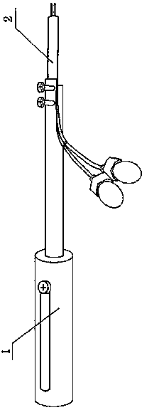
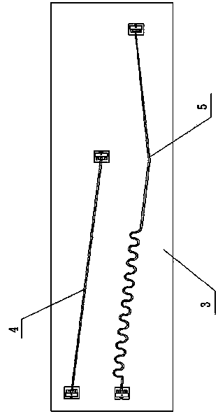
[0019] A simple and low-cost test method, including test fixtures and test boards, two transmission lines to be tested with different lengths are designed on the same level of the test board, named X1 and X2 respectively, as test structures A and B, and the wiring environment Try to be as consistent as possible, where the length of X1 is 11 inches, the length of X2 is 5 inches, and the length difference between X1-X2 is 6 inches. The two ends of the test line are respectively connected to the test points through via holes;

[0020] The S parameters of structure A measured through the transmission line X1 include: IL(A)=11inch transmission line loss + 2 PCB via hole losses + probe loss + uncertain influence of test fixtures;

[0021] The S parameters of structure B measured through the transmission line X2 include: IL(B)=5inch transmission line loss+2 PCB via hole loss+probe loss+test fixture uncertainty influence;

[0022] Calculate the loss formula per inch after the differen...

Embodiment 2

[0024] When designing and testing the transmission line loss of a certain material, such as IT150DA board, design 8-layer board, 4 signal layers, two surface layers and two inner layers, it is necessary to investigate the loss of these four layers of 85 ohm differential transmission lines. Make a test strip next to the motherboard, which can more truly reflect the PCB characteristics of the product. After the PCB processing is completed, take the test strip to the laboratory, use VNA and SMA probes for measurement, and change the PCB working environment, for example, take 3 points between 25 and 75 degrees, 25 degrees, 50 degrees, and 75 degrees. Next do the measurement. After doing differential calculations, the IT150DA sheet is stacked in this structure, and the loss characteristics per inch are obtained in different temperature environments.


PUM


Abstract

The invention discloses a simple low-cost test method. The simple low-cost test method comprises a test fixture and a test plate. Two tested conveying lines with different lengths are designed on the same layer of the test plate and named as X1 and X2 respectively to serve as a test structure A and a test structure B, the length difference of X1-X2 is at least larger than 4 inches, and the two ends of a test line are connected to a test point through passing holes; the short line X2 can not be too short; the parameter S, tested through the conveying line X1, of the structure A comprises that IL (A) = loss of the conveying line X1 + passing hole loss of 2 PCBs + loss of a probe + uncertain influence of the test fixture; the parameter S, tested through the conveying line X2, of the structure B comprises that IL (B) = loss of the conveying line X2 + passing hole loss of the 2 PCBs + loss of the probe + uncertain influence of the test fixture; the loss formula of each inch after difference between the test structure A and the test structure B is calculated is obtained: dB/inch loss = (IL(A) - IL(B))/(X2-X1), and the loss value of each inch of the conveying lines at different frequency points can be obtained through the formula.

Description

technical field [0001] The invention relates to the field of electronics, signal measurement and PCB LAYOUT design. technical background [0002] At present, the VNA is generally used to test the S parameters of the transmission line for the high-speed signal loss test, and the requirements are very strict when making the test board. For the accuracy of the test, the test fixture is required to be as accurate as possible from the probe to the CABLE. High-precision fixtures, such as the microwave probe GGB, are used in the test, which are expensive and require strict operation. If you are not careful, the test probe will be damaged and need to be shipped to the original factory in the United States for repair. AFR, TRL calibration design is used, which requires high requirements for design test pieces and measurement methods. Therefore, the test cost is high, the test cycle is long, and the test is difficult. This is a major disadvantage of the plate loss test. It is neces...

Claims


Application Information

Patent Timeline
IPC IPC(8): G01R31/00
Inventor 王素华
Owner LANGCHAO ELECTRONIC INFORMATION IND CO LTD
Why Eureka
Try Eureka