Method for estimating crosstalk magnitude, caused by electromagnetic interference of external transient state, of PCB microstrip transmission line

A technology of microstrip transmission line and electromagnetic interference, which is applied in the direction of electrical digital data processing, special data processing applications, instruments, etc., and can solve the problem of large amount of calculation of microstrip line signals

Active Publication Date: 2014-09-03
HARBIN ENG UNIV
View PDF5 Cites 13 Cited by
  • Summary
  • Abstract
  • Description
  • Claims
  • Application Information

AI Technical Summary

Problems solved by technology

[0006] To sum up: the existing literature on the microstrip line signal integrity research in complex electromagnetic environment is either too much calculation or the research has limitations. Based on this, the present invention proposes a new algorithm based on the reciprocity theorem to calculate Coupling between the space electromagnetic field and the microstrip line, and using the finite difference time domain (FDTD) method to calculate the transient response of the crosstalk on the microstrip transmission line caused by this coupling

Method used


Image

  • Method for estimating crosstalk magnitude, caused by electromagnetic interference of external transient state, of PCB microstrip transmission line
  • Method for estimating crosstalk magnitude, caused by electromagnetic interference of external transient state, of PCB microstrip transmission line
  • Method for estimating crosstalk magnitude, caused by electromagnetic interference of external transient state, of PCB microstrip transmission line

Examples


Embodiment Construction

[0041] The present invention will be further described below in conjunction with the accompanying drawings.

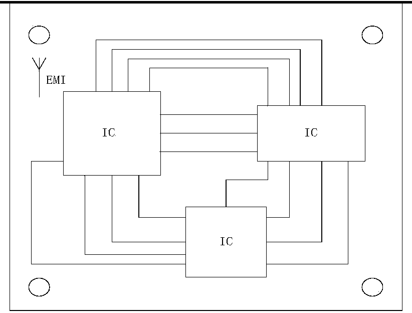
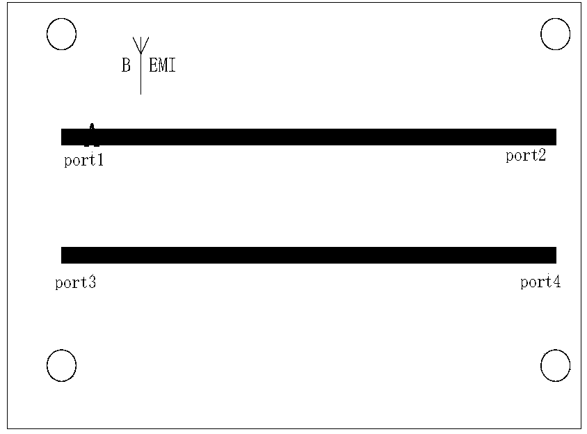
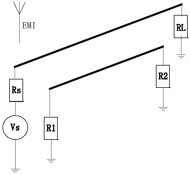
[0042] Aiming at the practical problems existing in real life, the present invention proposes a novel problem of estimating the transient response of crosstalk caused when PCB microstrip lines are disturbed by external electromagnetic pulses in a complex electromagnetic environment. The invention can be divided into two parts, one part is the coupling between the sudden electromagnetic pulse in the air and the PCB microstrip line, and the other part is the transient response of the microstrip transmission line crosstalk caused by coupling to the microstrip line.

[0043] The first part of the problem has been studied at home and abroad, such as Taylor, Satterwhite, Harrion, etc. Many of the models they studied have been widely used and solved some problems related to the interaction between electromagnetic pulse (EMP) and lightning and power communication cables. But t...


PUM


Abstract

The invention belongs to the field of estimation and protection of electromagnetic interference in communication engineering, and particularly relates to a method for estimating the crosstalk magnitude, caused by electromagnetic interference of an external transient state, of a PCB microstrip transmission line, wherein the method is for estimating the size of transient state response of a PCB which works normally when the PCB is interfered by external sudden electromagnetic pulses in study of the integrity of PCB microstrip line signals under complex electromagnetic environments in space. The method comprises the steps that a coupling model between a PCB microstrip line and transient state electromagnetic interference in the air is established; the coupling between the PCB microstrip line and the transient state electromagnetic interference in the air is calculated according to the coupling model between the PCB microstrip line and the transient state electromagnetic interference in the air; coupling voltages are added to the microstrip transmission line, and discretization is carried out on a transmission line equation by utilizing an FDTD method; simulation is carried out on a crosstalk equation after discretization by utilizing Matlab, and a crosstalk result is obtained. According to the method for estimating the crosstalk magnitude, caused by the electromagnetic interference of the external transient state, of the PCB microstrip transmission line, the crosstalk of spacial electromagnetic interference on the PCB microstrip line is calculated through a simple method, calculation amount is reduced, and efficiency is improved.

Description

technical field [0001] The invention belongs to the field of estimation and protection of electromagnetic interference in communication engineering. Specifically involved in the study of PCB microstrip line signal integrity in a space-complex electromagnetic environment, the estimation of the transient response of a normally working PCB board when it is subjected to sudden electromagnetic pulse interference from the outside world The method of crosstalk size of PCB microstrip transmission line caused by transient electromagnetic interference. Background technique [0002] The rapid development of integrated circuit technology makes electronic circuits more and more complex, and printed circuit boards (PCBs) are gradually becoming high-density, high-speed, and multi-layered. High speed will inevitably cause the frequency to rise, which will bring high-frequency electromagnetic field coupling. This is the main factor restricting the development of PCB to high speed and high ...

Claims


Application Information

Patent Timeline
Patent Type & Authority Applications(China)
IPC IPC(8): G06F19/00
Inventor 孙亚秀李千卓庆坤姜庆辉
Owner HARBIN ENG UNIV
Why Eureka
Try Eureka