
High-Pressure Fuel Pump For A Fuel Injection System

A technology of fuel injection and high-pressure pumps, which is applied in the direction of fuel injection pumps, fuel injection devices, charging systems, etc., can solve problems such as rapid stop of internal combustion engines, and achieve the effect of improving service life

Inactive Publication Date: 2014-09-03
ROBERT BOSCH GMBH
View PDF6 Cites 2 Cited by
  • Summary
  • Abstract
  • Description
  • Claims
  • Application Information

AI Technical Summary

Problems solved by technology

It has the disadvantage of causing the internal combustion engine to stop quickly

Method used


Image

  • High-Pressure Fuel Pump For A Fuel Injection System
  • High-Pressure Fuel Pump For A Fuel Injection System
  • High-Pressure Fuel Pump For A Fuel Injection System

Examples


Embodiment Construction

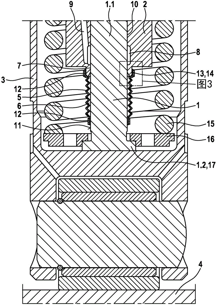
[0018] figure 1 The shown cartridge pump comprises a pump piston 1 whose first end 1.1 is housed in a hollow cylinder 2 of the cylinder head and whose second end 1.2 is indirectly supported on a camshaft 4 via a cup-shaped part 3 superior. The second end 1 . 2 forms a piston bottom 17 on which a spring seat 16 is located, wherein the spring seat 16 serves to accommodate the spring 15 . The spring force of the spring 15 keeps the cup part 3 and the pump piston 1 in contact with the camshaft 4 . The hollow cylinder 2 is surrounded by the spring 15 and the cup-shaped part 3 .

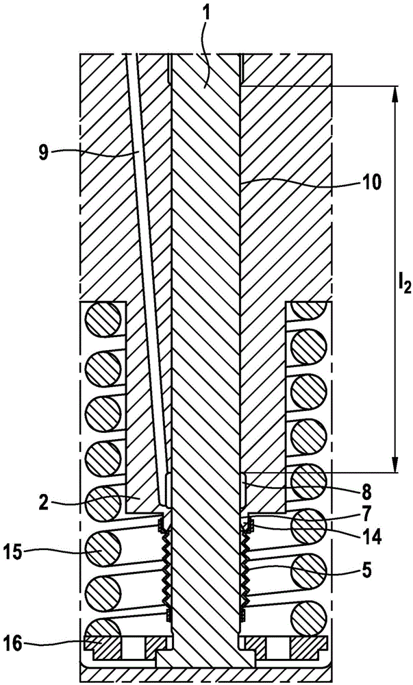
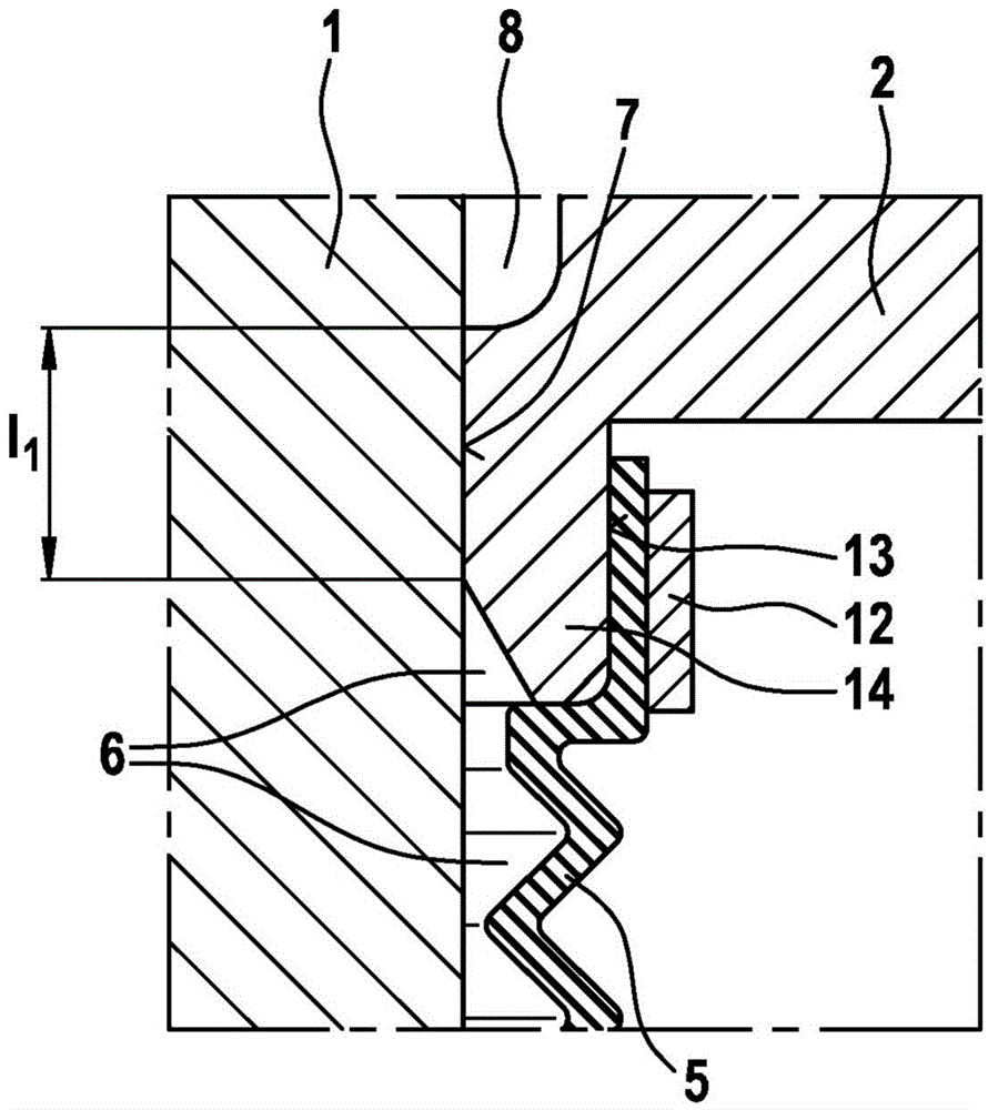
[0019] To seal the guide gaps 7 , 10 , the pump piston 1 and the hollow cylinder 2 are connected via a seal 5 designed as a bellows. The seal 5 is fastened on one side to the outer peripheral surface 11 of the pump piston 1 and on the other side to the outer peripheral surface 13 of a neck ring 14 which rests on the hollow cylinder 2 . These fastenings are carried out by means of a crimped ring 12 whic...


PUM


Abstract

The invention relates to a high-pressure fuel pump, in particular a plug-in pump, for a fuel injection system for injecting fuel into the combustion chamber of an internal combustion engine, comprising a pump piston (1) which can carry out a stroke movement and the first end (1.1) of which is guided in a hollow cylinder (2) and the second end (1.2) is indirectly supported on a camshaft or eccentric shaft (4) via a cup-shaped component (3). The high-pressure fuel pump further comprises a seal (5) which is preferably designed as a bellows and which is fixed to the pump piston (1) at one end and to the hollow cylinder (2) at the other end, thereby forming an annular space (6). According to the invention, a guide gap (7) which is formed between the pump piston (1) and the hollow cylinder (2) is designed as an annular gap seal in order to seal the annular space (6). Furthermore, the guide gap (7) opens into an annular groove (8) which is formed in the hollow cylinder (2) and which is connected to a leakage line (9) in order to recirculate a leakage quantity.

Description

technical field [0001] The invention relates in particular to a high-pressure fuel pump for a fuel injection system, having the features of the preamble of claim 1 , which is designed as a cartridge pump for injecting fuel into a combustion chamber of an internal combustion engine. . Background technique [0002] A high-pressure fuel pump for internal combustion engines is known, for example, from DE 10 2008 002 195 A1, which is designed as a cartridge pump. The high-pressure fuel pump includes a piston, one end of which protrudes from a hollow cylinder and is reciprocated by a compression spring onto a radial projection of a drive shaft in the hollow cylinder, wherein the drive shaft surrounds the An axis for orientation. In order to separate fuel and lubricating oil, in particular to prevent the fuel from penetrating into the oil supply cavity of the internal combustion engine, this document proposes that the end of the piston protruding from the hollow cylinder and the ...

Claims


Application Information

Patent Timeline
IPC IPC(8): F04B1/04F04B53/04
CPCF02M59/102F04B1/0408F04B1/0426F04B1/0443F02M59/442
Inventor M·舍特尔
Owner ROBERT BOSCH GMBH
Learn More