Laying method of casting system

A laying method and pouring system technology, which is applied to casting molding equipment, metal processing equipment, casting molds, etc., can solve the problem of affecting the surface quality of castings, the fluidity of molten steel, the laying operation of the pouring system is not fine, and the runners are not on the same plane, etc. problems, to achieve the effects of good sealing, fast laying speed, and reduced concentrated labor intensity

Active Publication Date: 2014-09-10
KOCEL STEEL
View PDF6 Cites 4 Cited by
  • Summary
  • Abstract
  • Description
  • Claims
  • Application Information

AI Technical Summary

Problems solved by technology

Due to the large number of gates in large steel castings, the gating system is complicated, and the available time of resin sand is only 40 minutes, which will largely lead to imprecise laying operations of the gating system
It directly leads to the problems that the runners are not on the same plane and the loose sand flows into the runners during the laying process of the pouring system, which affects the surface quality of the castings and the fluidity of the molten steel during the pouring process.

Method used


Image

  • Laying method of casting system
  • Laying method of casting system
  • Laying method of casting system

Examples


Embodiment Construction

[0020] Describe working process of the present invention below in conjunction with accompanying drawing.

[0021] A method for laying a pouring system, the steps are as follows:

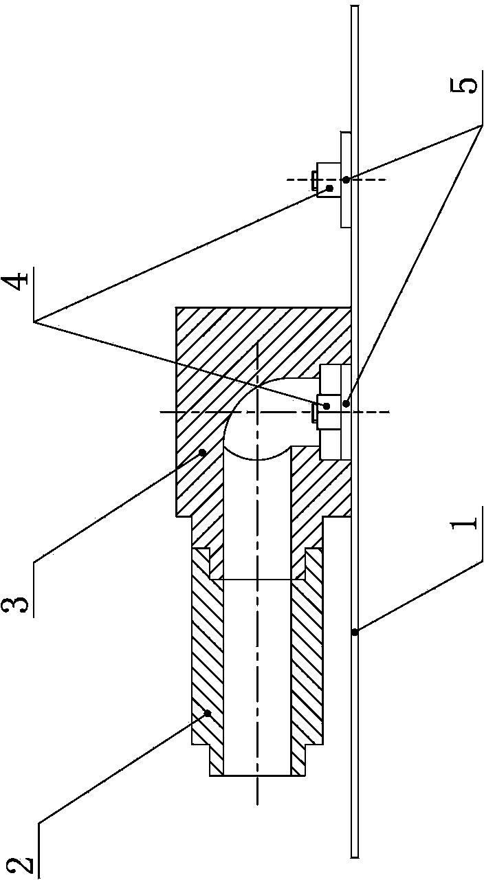
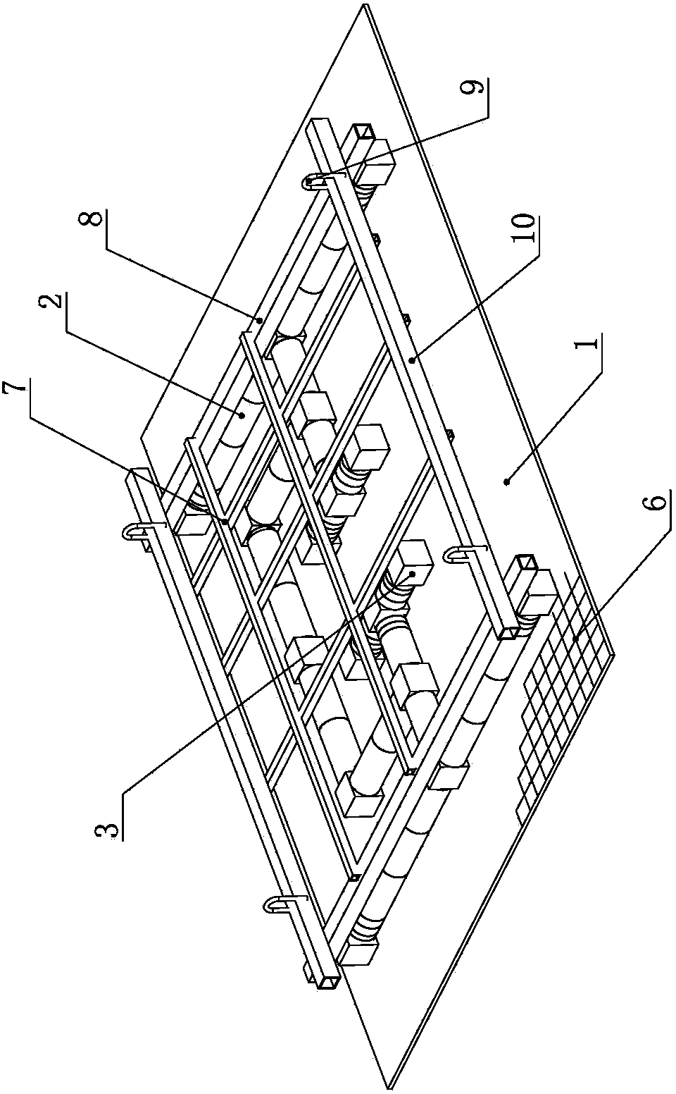
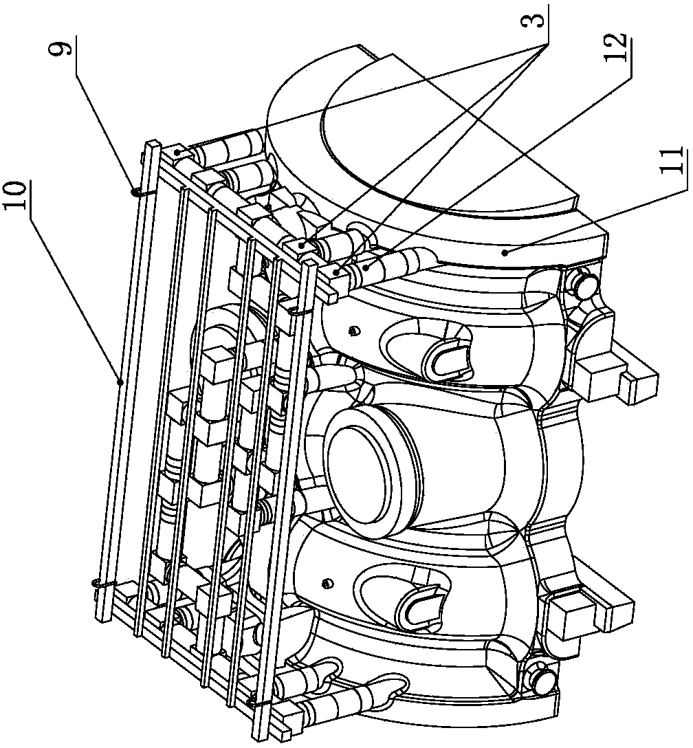
[0022] 1) Fix a number of gate positioning platforms 5 on the horizontally placed work surface 1. The placement positions of the gate positioning platforms 5 correspond to the positions of the inner gates of the mold 11 one by one; the outer diameter of the gate positioning platforms 5 corresponds to the outlet of the runner The calibers of the porcelain tubes 3 match; the working table 1 is provided with positioning grid lines 6 vertically and horizontally, and the gate positioning table 5 is positioned by the positioning grid lines. The working table 1 is made of ferromagnetic material steel plate, and its size is 7000×5000×10mm , The sprue positioning table 5 is made of 12mm thick wooden material, the sprue positioning table 5 is equipped with a magnetic base 4, and the magnetic base 4 and the wor...


PUM


Abstract

The invention relates to a laying method of a casting system in the technical field of casting. The laying method comprises the following steps: firstly, a plurality of gate positioning tables are fixed on a working table; then, a lifting bracket is arranged above the working table; cross gates are mounted at the lower side of the lifting bracket; ports of ceramic pipes in outlets of the cross gates are coated at the outer sides of the gate positioning tables; a mold is overturned to enable ingates to be upwards; ingate ceramic pipes are inserted in all the ingates, so that the upper end surfaces of the ceramic pipes in the ingates are positioned on the same horizontal plane; when sand flows to the upper port positions of the ceramic pipes in the ingates, the sand is scraped flatly; the lifting bracket is lifted to place at the upper side of the mold, so that the ceramic pipes in the ingates are in inserted connection with the ceramic pipes in the outlets of the cross gates one by one; inlets of the cross gates are connected with straight gates arranged outside; the sand flows again; when the sand is flatten to the positions of the cross gates, the lifting bracket is disassembled; the shaping of flowing sand is continued; and finally, the sand mold is overturned to finish the laying. The laying method can quickly build the casting system; the sealing among the ceramic pipes is excellent; and the quality of castings is better. The laying method is suitable for the production of bottom pouring type castings.

Description

technical field [0001] The invention relates to a laying method of a pouring system, in particular to a laying method of a pouring system of a large steel casting. Background technique [0002] When designing the casting process of large steel castings, considering the impact on the core and cavity and reducing the oxidation of molten steel, a bottom pouring gating system is generally used to allow molten steel to flow from the bottom of the casting into the cavity of the mold, and through process calculation In order to ensure the smoothness of the molten steel during the filling process and reduce the entrainment and splash caused by turbulent flow, the runners must be laid flat; due to the size and size of large castings and The tonnage is large, and the static pressure head of the molten steel is very large during the pouring process. If the strength of the pouring system is low, it is easy to cause sand washing or fire escape. [0003] In the actual molding process, th...

Claims


Application Information

Patent Timeline
Patent Type & Authority Applications(China)
IPC IPC(8): B22C9/08
Inventor 何启良闫新飞杨建马发仁唐钟雪
Owner KOCEL STEEL
Why Eureka
Try Eureka