
Method for assembling screw rod and rolling bearing assembly

A technology of rolling bearing and assembly method, applied in the direction of rolling contact bearings, bearing components, shafts and bearings, etc., can solve problems such as permanent damage, achieve continuous lubrication, simple assembly method, and prevent dust from entering.

Inactive Publication Date: 2014-09-10
ZHEJIANG UNIV
View PDF4 Cites 9 Cited by
  • Summary
  • Abstract
  • Description
  • Claims
  • Application Information

AI Technical Summary

Problems solved by technology

Because the ball screw pair only bears axial load, the radial force and overturning moment will cause the ball screw pair to generate additional surface contact stress and other undesirable loads, resulting in permanent damage

Method used


Image

  • Method for assembling screw rod and rolling bearing assembly
  • Method for assembling screw rod and rolling bearing assembly
  • Method for assembling screw rod and rolling bearing assembly

Examples


Embodiment Construction

[0032] Below in conjunction with embodiment further illustrate the present invention.

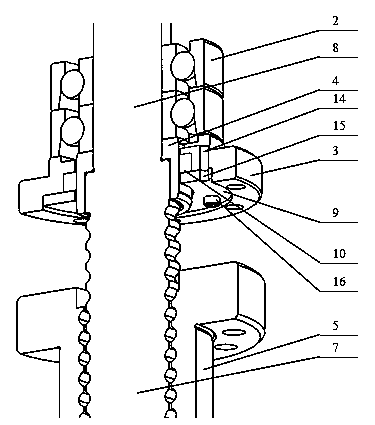
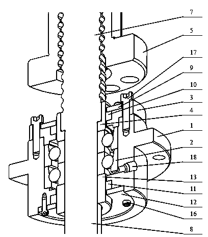
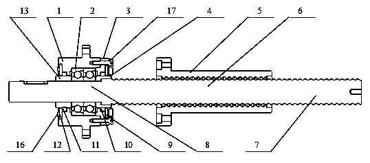
[0033] A screw and rolling bearing assembly assembly method of the present invention, said screw and rolling bearing assembly comprises screw fixing sleeve 1, rolling bearing 2, screw flange 3, screw cover 14, ball nut 5, ball screw 6 , Gland I 9, rubber sealing ring I 10, rubber sealing ring II 11, gland II 12, screw cover II 13, screw I 16, screw II 17, screw fixing sleeve oil hole 18. Ball screw 6 is divided into leading screw raceway section 7 and leading screw connection section 8, leading screw flange oil leakage hole 14 is arranged on leading screw flange 3, gland oil leakage hole 15 is arranged on gland 19. The method steps are as follows.

[0034] (1) Preparations

[0035] (1.1) Selection of parts such as rolling bearings

[0036] According to the requirements of load capacity and transmission accuracy, select the appropriate rolling bearing 2 matching the ball screw 6, such as ...


PUM


Abstract

The invention discloses a method for assembling a screw rod and rolling bearing assembly. The method comprises the steps of mounting a screw rod flange, mounting a rolling bearing, mounting a screw rod fixing sleeve, fixing a screw rod flange and the screw rod fixing sleeve and finally obtaining the assembled screw rod and rolling bearing assembly. The method is simple, convenient and easy to achieve, and the assembled screw rod and rolling bearing assembly is tight, firm and clean. The parallelism between the screw rod and a working table linear guide rail in the horizontal and vertical directions, the coaxiality between a bearing seat and a ball nut and the rotating precision of a ball screw are guaranteed, namely, radial runout precision and axial float precision are guaranteed, continuous lubrication can be achieved, leakage of lubricating oil inside is avoided, external dust is prevented from entering the assembly, and long-term stable work of parts is facilitated.

Description

technical field [0001] The invention belongs to the field of mechanical manufacturing and assembly, and in particular relates to an assembly method of a lead screw and a rolling bearing assembly. Background technique [0002] Assembly is the later link in the manufacturing process of injection molding machine products. How to correctly install the various parts that make up the machine together to form a complete product and achieve the desired accuracy is a problem to be solved in production engineering. After carefully designing the assembly method, while ensuring the performance of the machine, the manufacturing cost can be significantly reduced, and the production efficiency can be greatly improved at the same time. [0003] The ball screw in the electric injection molding machine is a precision transmission component. In addition to ensuring the horizontal and vertical parallelism between the screw and the linear guide rail of the worktable, and the coaxiality between ...

Claims


Application Information

Patent Timeline
Patent Type & Authority Applications(China)
IPC IPC(8): B23P19/04
CPCF16C35/063F16C19/163F16C19/542B23P11/00B23P11/025
Inventor 李凌丰王伟陈豪
Owner ZHEJIANG UNIV
Learn More