
Tidal flat amphibious machine

A multi-purpose machine, water and land technology, applied in the field of machinery, can solve the problems of affecting oil absorption, slow travel speed, inconvenient travel, etc., and achieve the effect of strong adaptability and great mobility

Active Publication Date: 2016-03-23
QINGDAO GUANGMING ENVIRONMENTAL TECH
View PDF6 Cites 0 Cited by
  • Summary
  • Abstract
  • Description
  • Claims
  • Application Information

AI Technical Summary

Problems solved by technology

For example, tidal flat farming, when harvesting various shellfish or seaweed, conventional harvesting tools are time-consuming and labor-intensive, and the efficiency is low
In addition, marine oil spills or oil spill accidents often occur. Due to the completely different nature of the area between land and water, and even various slopes, conventional oil suction ships have certain limitations in the process of entering the sea from land. The speed is slow, which affects oil absorption and causes further expansion of the oil surface
Furthermore, due to environmental pollution, a large number of algae gather, which not only destroys the water body, but also affects the operation of the beach, and there are various floating garbage in the water area, which greatly affects the quality of the water body and the image of the city.
[0003] At present, although there are also amphibious equipment, such equipment still has the following disadvantages: 1. It is inconvenient to travel in transitional areas between land, tidal flats, and waters, and has certain limitations; 2. It is large and heavy , the power required is large, and the operating room and power equipment are fixed with the body, which lacks flexibility; 3. The function is single, and conventional equipment can only achieve one function, either an oil suction ship, or a weeding (algae) machine, or a Excavators, etc.

Method used


Image

  • Tidal flat amphibious machine
  • Tidal flat amphibious machine
  • Tidal flat amphibious machine

Examples


Embodiment 1

[0032] After entering the oil spill area, the oil skimmer 21 can be replaced on the spot, and other structures remain unchanged. The oil skimmer 21 is supported by the hydraulic telescopic arm type functional device to carry out the oil collection operation, and the flowable oil can be recovered.

Embodiment 2

[0034] When needing weeding, the lawn mower 22 can be replaced on the spot, and the hydraulic telescopic arm type functional device can be used to support the lawn mower 22 to clean up weeds, and can cut and clean weeds such as reeds and water hyacinths.

Embodiment 3

[0036] When it is necessary to reclaim blocky oil lumps or cut weeds or floating algae on the tidal flats, replace the recovery shovel 23 on the spot, and the hydraulic telescopic arm type functional device can be used to support the recovery shovel 23 for recovery operations.


PUM


Abstract

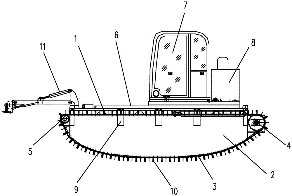
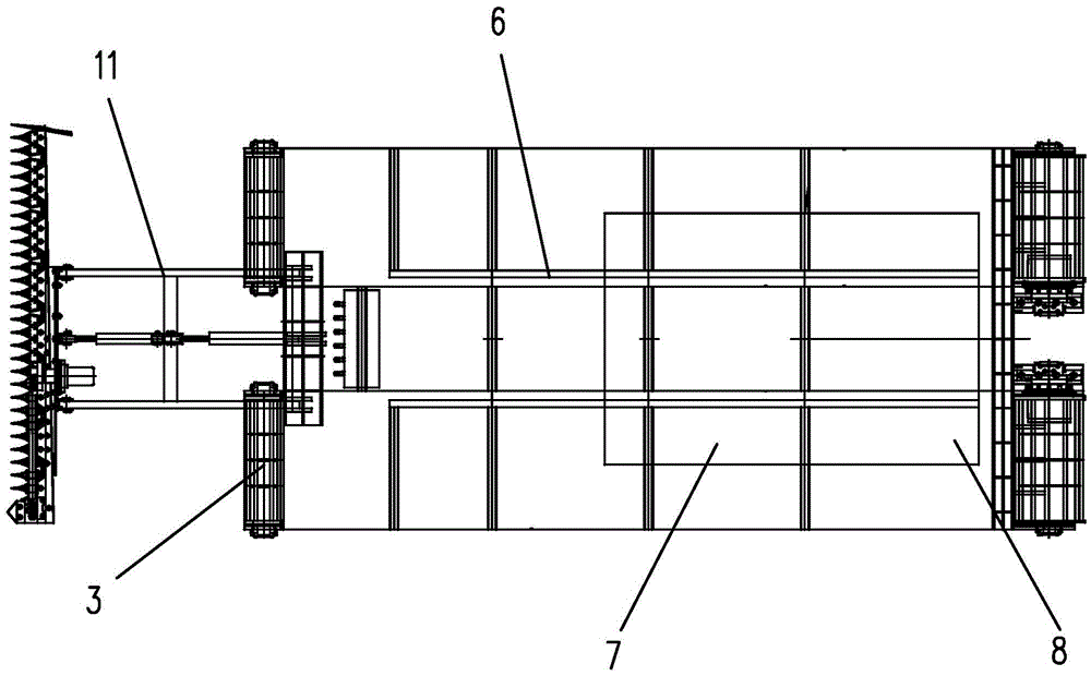
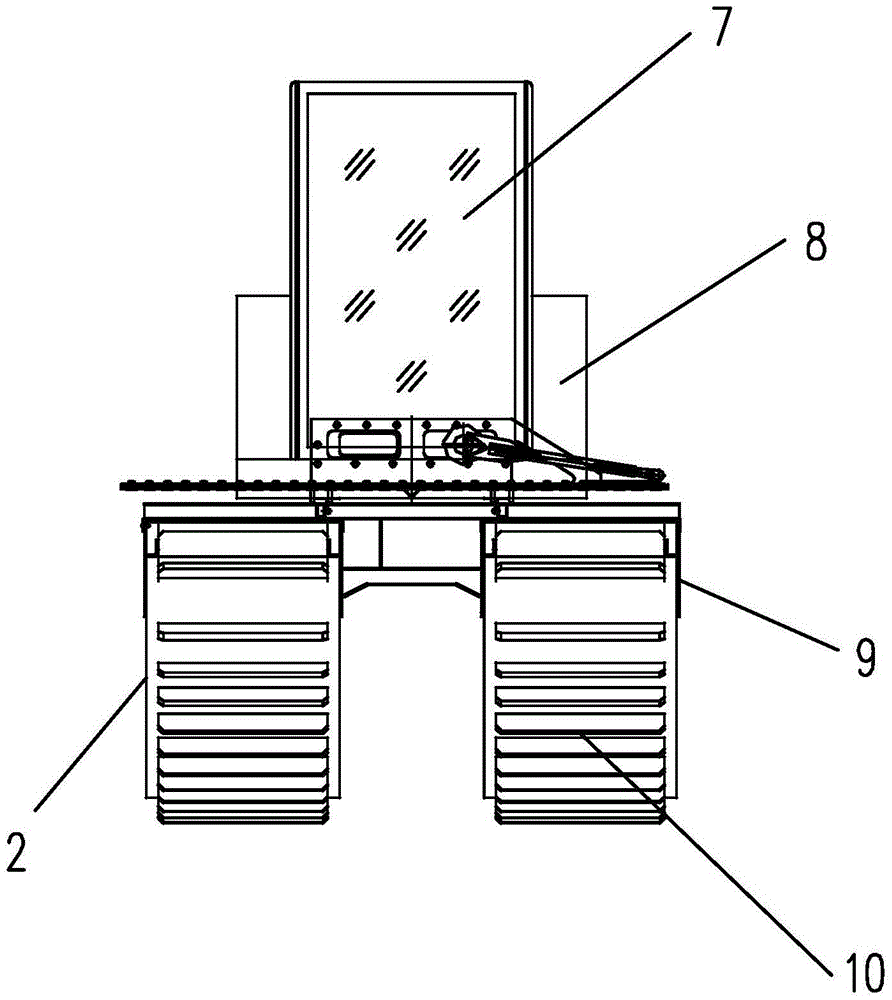
The invention relates to a land and water multi-purpose machine on beaches. The machine comprises a deck, wherein floating boxes are arranged below the deck, deck supporting plates are arranged on the outer sides of the floating boxes, the deck and the floating boxes are connected by bolts on the deck supporting plates, a driving device is arranged at one end of each floating box, a driven device is arranged at the other end of each floating box, tracks are respectively arranged at the peripheries of the driving devices, the floating boxes and the driven devices, the position above the deck is connected with a machine frame by bolts, a cab and a power station are arranged above the machine frame, the machine frame comprises a guide rail which is fixed on the deck, guide blocks matched with the guide rail are respectively arranged below the cab and the power station, a power mechanism is arranged between the cab and the power station, and a hydraulic telescopic arm type function device is arranged in front of a machine body. By adoption of a floating box type track power device, the driving operation on land and in water can be realized, the driving operation on beach areas between the land and the water can also be realized, the maneuverability is great, and the adaptability is strong. By adoption of the curve type floating boxes, and the movable cab and the movable power station, the whole machine is convenient to climb or drive in other irregular regions.

Description

technical field [0001] The present invention relates to the mechanical field. In particular, it relates to a device capable of traveling on land, tidal flats and water areas and realizing multiple functions. Background technique [0002] At present, due to the completely different nature of waters and land areas, coupled with the limitation of the structure and function of the operating equipment itself, ordinary operating equipment can only operate on land, and operating ships can only operate on water. Have ideal working equipment. With the development of society, the demand for operations in tidal flats is increasing. For example, tidal flat farming, when various shellfish or seaweed are harvested, conventional harvesting tools are time-consuming and labor-intensive, and the efficiency is low. In addition, marine oil spills or oil spill accidents often occur. Due to the completely different nature of the area between land and water, and even various slopes, conventiona...

Claims


Application Information

Patent Timeline
Patent Type & Authority Patents(China)
IPC IPC(8): B60F3/00B62D55/06E02B15/10A01D44/00
Inventor 何锐王忠岱刘晓丹杨阳李俊姜家康
Owner QINGDAO GUANGMING ENVIRONMENTAL TECH
Learn More