
Bidirectional spiral electrostatic spinning device

An electrospinning, bidirectional helical technology, used in textiles and papermaking, filament/thread forming, feeding solution to spinnerets, etc. Fiber film quality and other issues, to reduce electrostatic interference and electric field concentration, easy automatic control, and improve the efficiency of electrospinning

Active Publication Date: 2014-09-10
XIAMEN UNIV
View PDF4 Cites 18 Cited by
  • Summary
  • Abstract
  • Description
  • Claims
  • Application Information

AI Technical Summary

Problems solved by technology

However, the array arrangement of multi-spinning nozzles is prone to produce uneven electric fields, and the mutual electric conduction between nozzles inhibits the influence, and the injection status of each nozzle is inconsistent, so it is difficult to ensure continuous and stable jet injection of each nozzle at the same time; and the static electricity between the jets The repulsion also increases the instability of the jet, resulting in a large difference in the shape and size of the nanofibers sprayed by each nozzle, which affects the quality of the prepared nanofiber film
In addition, most traditional electrospinning devices use standard injection spinning nozzles as nozzles, which have disadvantages such as easy clogging and difficult cleaning, which hinder their industrialization.

Method used


Image

  • Bidirectional spiral electrostatic spinning device
  • Bidirectional spiral electrostatic spinning device
  • Bidirectional spiral electrostatic spinning device

Examples


Embodiment Construction

[0030] The present invention will be further described below in conjunction with drawings and embodiments.

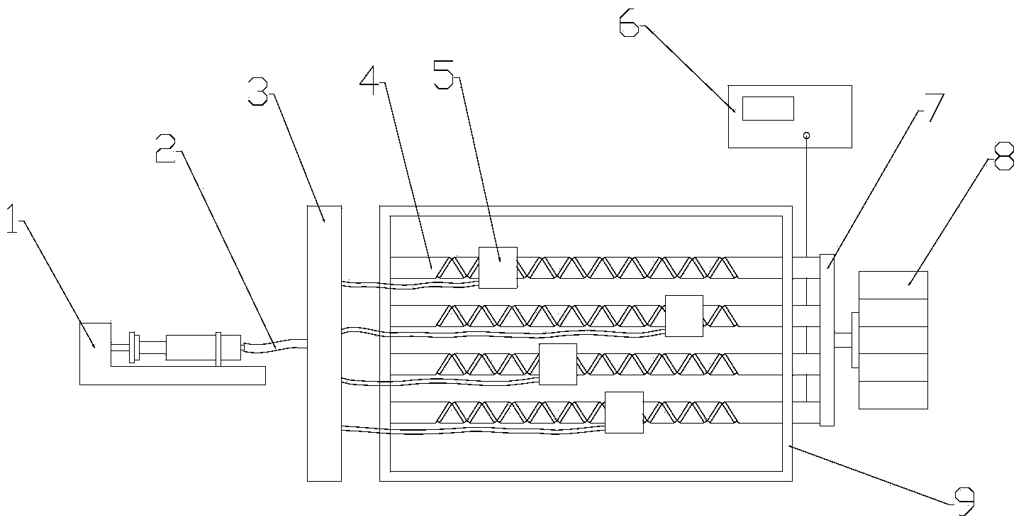
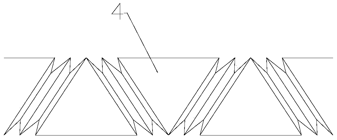
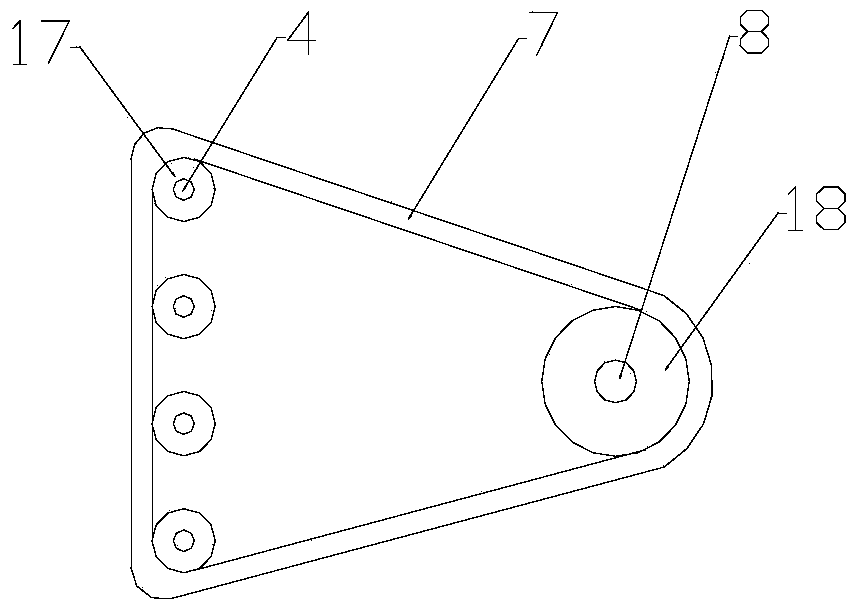
[0031] see Figure 1~6 , the embodiment of the present invention is provided with two-way threaded guide rod 4, liquid storage slider 5, vertical slide rod 14, guide rail 15, frame 9, controllable injection device 1, liquid conduit 2, liquid dispensing device 3, high voltage power supply 6 , air pump 10, pressure regulating valve 11, gas conduit 12, partition 16, motor 8, driven pulley 17, driving pulley 18, V-shaped belt 7, air hole array 19 and collection device 13.

[0032]The two-way threaded guide rod 4 is clamped and fixed on the frame 9, and the end of each two-way threaded guide rod 4 is equipped with a driven pulley 17, and the driven pulley 17 is connected to the motor 8 through the V-shaped belt 7. The driving pulley 18 of the main shaft is connected to realize the rotation of multiple bidirectional threaded guide rods 4 driven by the motor 8 at the same tim...


PUM


Abstract

The invention discloses a bidirectional spiral electrostatic spinning device, and relates to an electrostatic spinning device. The bidirectional spiral electrostatic spinning device is provided with bidirectional threaded guide rods, liquid storage sliders, vertical slide bars, guide rails, a framework, a controllable injection device, a liquid guide pipe, a liquid distributing device, a high-voltage power source, air pumps, pressure regulating valves, air guide pipes, partition plates, motors, driven belt pulleys, driving belt pulleys, V-shaped belts, air hole arrays and collecting devices. The bidirectional spiral electrostatic spinning device has the advantages that large-area and multi-jet injection effects can be realized by the aid of the bidirectional threaded guide rods, so that the electrostatic spinning efficiency further can be improved, phenomena of electrostatic interference among spinning jets and electric field concentration can be reduced, uniform distribution of nano-fibers on collecting plates can be promoted, the thickness uniformity of collected nano-fiber membranes can be improved, the quality of the nano-fiber membranes can be enhanced, the multiple jets can be assuredly stably and quickly injected, and large-area uniform nano-membranes can be collected; the bidirectional spiral electrostatic spinning device is applicable to injection devices with different bidirectional threaded guide rods and different thread shapes, and the lengths, the quantities and the shapes of the bidirectional threaded guide rods of the injection devices can be different from one another.

Description

technical field [0001] The invention relates to an electrospinning device, in particular to a bidirectional helical electrospinning device which utilizes a bidirectional thread guide rod to realize large-area and multi-jet spraying. Background technique [0002] Electrospinning technology can successfully prepare most polymers and their copolymers, capped copolymers, derivatives, etc. into electrospun fibers in the range of 3 nm to 5 μm. The principle is: under the action of a high-voltage electrostatic generator, spinning A high-voltage electrostatic field is formed between the liquid injection device and the nanofiber receiving device; the polymer solution is charged under the action of the high-voltage electric field and is stretched by the electric field force, deforming to produce a Taylor cone; when the electric field force is large enough, the liquid droplets overcome the surface tension A charged jet is formed, which accelerates towards the collector; it bends and st...

Claims


Application Information

Patent Timeline
Patent Type & Authority Applications(China)
IPC IPC(8): D01D5/00D01D1/06
Inventor 郑高峰姜佳昕吴佳静孙玲玲郑建毅孙道恒
Owner XIAMEN UNIV
Learn More