A multi-stage tangential magnetic field plasma thruster with channel magnetic field guiding structure

A technology of magnetic field guidance and cusp magnetic field, which is applied in the field of plasma thrusters, can solve the problems of long processing cycle of samarium cobalt permanent magnet materials, difficult adjustment of magnetic interface angle, and inconvenient adjustment, so as to shorten the processing cycle and avoid Effect of weakened magnetism and simple structure

Active Publication Date: 2016-08-24
HARBIN INST OF TECH
View PDF6 Cites 3 Cited by
  • Summary
  • Abstract
  • Description
  • Claims
  • Application Information

AI Technical Summary

Problems solved by technology

[0005] The present invention aims to solve the problem that the magnetic field configuration of the existing thruster and the position of the tip of the magnetic mirror cannot be conveniently adjusted according to the change of the section of the discharge channel, the angle of the magnetic interface at the tip of the magnetic mirror is not easy to adjust, and the samarium used for variable section experiments Cobalt permanent magnet materials have long processing cycle and high price, and then provide a multi-stage cusp magnetic field plasma thruster with a channel magnetic field guiding structure

Method used


Image

  • A multi-stage tangential magnetic field plasma thruster with channel magnetic field guiding structure
  • A multi-stage tangential magnetic field plasma thruster with channel magnetic field guiding structure
  • A multi-stage tangential magnetic field plasma thruster with channel magnetic field guiding structure

Examples


specific Embodiment approach 1

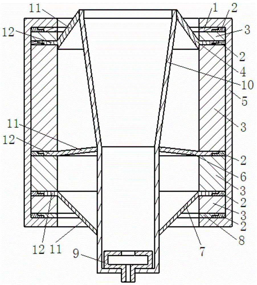
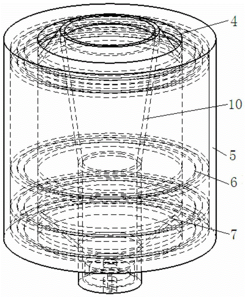
[0013] Specific implementation mode one: combine Figure 1-Figure 8 Explain, a kind of multi-stage tangent magnetic field plasma thruster with the channel magnetic field guiding structure of the present embodiment comprises ceramic sleeve 10, motor case 5 and four permanent magnets 3, and permanent magnet 3 is the annular permanent magnet, Four permanent magnets 3 are sequentially arranged from top to bottom, and the middle part of four permanent magnets 3 is arranged with ceramic sleeve 10, and the large-diameter port of ceramic sleeve 10 faces upward, and four permanent magnets 3 are clamped on the Together;

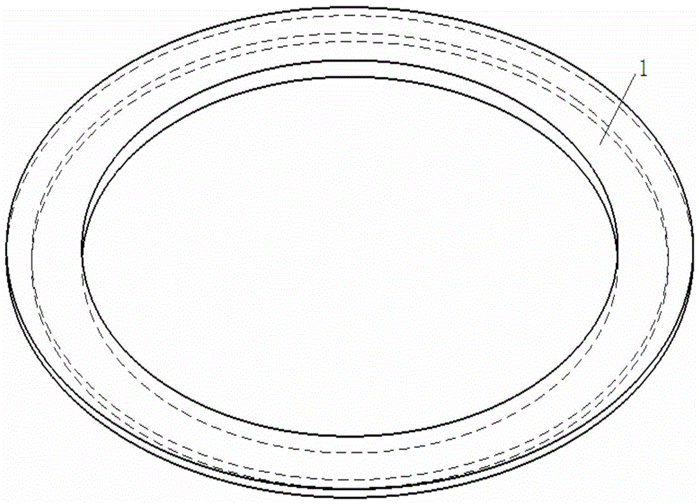
[0014] It also includes five magnetically conductive rings and five nonmagnetically conductive matching rings 2; the five magnetically conductive rings are the first magnetically conductive ring 1, the second magnetically conductive ring 4, the third magnetically conductive ring 6, and the fourth magnetically conductive ring. The magnetic ring 7 and the fifth magnetic...

specific Embodiment approach 2

[0018] Specific implementation mode two: combination Figure 1-Figure 7 Note that the five magnetic permeable rings in this embodiment are all made of pure iron. Such an arrangement is cheap and easy to obtain, and is conducive to heat conduction. Others are the same as in the first embodiment.

specific Embodiment approach 3

[0019] Specific implementation mode three: combination Figure 1-Figure 7 Note that the five non-magnetic mating rings 2 in this embodiment are all made of aluminum alloy. With such arrangement, the heat deposited on the magnetic conduction ring can be conducted to the engine casing, which is beneficial to heat dissipation. Others are the same as in the first or second embodiment.


PUM


Abstract

A multi-stage tangential magnetic field plasma thruster with a channel magnetic field guiding structure, which relates to an electric thruster to solve the problem that the magnetic field configuration and the tip position of the magnetic mirror of the existing thruster cannot be achieved according to the change of the discharge channel section It is convenient and adjustable, the angle of the magnetic interface at the tip of the magnetic mirror is not easy to adjust, and the long processing period and high price of the samarium cobalt permanent magnet material used for variable cross-section experiments include ceramic sleeves, engine casings and four permanent magnets. The permanent magnet is a ring-shaped permanent magnet, and the four permanent magnets are arranged sequentially from top to bottom. A ceramic sleeve is arranged in the middle of the four permanent magnets. The large-diameter port of the ceramic sleeve faces upward, and the four permanent magnets pass through the engine casing. Snapped together, it also includes five magnetically permeable rings and five non-magnetically permeable matching rings; the five magnetically permeable rings are the first magnetically permeable ring, the second magnetically permeable ring, the third magnetically permeable ring, the fourth The magnetic conduction ring and the fifth magnetic conduction ring. The invention is applied in the aerospace field.

Description

technical field [0001] The invention relates to an electric thruster, in particular to a multi-stage tangent magnetic field plasma thruster with a channel magnetic field guiding structure. Background technique [0002] The multi-stage cusp magnetic field plasma thruster is a new type of electric thruster developed on the basis of the Hall thruster. The thruster is composed of multi-stage reverse ring permanent magnets to form a tangential magnetic field, and the periphery of the central discharge channel area is a ceramic sleeve. Electrons are emitted from the hollow cathode at the exit of the channel, and move to the anode upstream of the channel under the action of the electric field. Due to the magnetic mirror effect at the tip of the tangent magnetic field, the electrons are effectively shielded and will not collide with the ceramic wall. Magnetic field confinement, high-speed reciprocating motion between two magnetic tips. During this process, electrons will move to t...

Claims


Application Information

Patent Timeline
Patent Type & Authority Patents(China)
IPC IPC(8): F03H1/00
Inventor 刘辉马成毓孙国顺陈蓬勃赵隐剑胡鹏于达仁
Owner HARBIN INST OF TECH
Why Eureka
Try Eureka