Self-circulation aging test system and test method for frequency converter

A technology of aging test and frequency converter, applied in the direction of instruments, measuring electricity, measuring devices, etc., can solve the problems of inconvenient operation, complicated configuration, unreal simulation conditions, etc., and achieve the effect of convenient operation and simple configuration

Inactive Publication Date: 2014-09-10
SHANGHAI GIE EM
View PDF10 Cites 24 Cited by
  • Summary
  • Abstract
  • Description
  • Claims
  • Application Information

AI Technical Summary

Problems solved by technology

[0007] In view of the above-mentioned defects in the existing main energy-saving frequency converter aging test circuit or complex configuration or inconvenient operation or low efficiency or unrealistic simulation condit

Method used


Image

  • Self-circulation aging test system and test method for frequency converter
  • Self-circulation aging test system and test method for frequency converter
  • Self-circulation aging test system and test method for frequency converter

Examples


example 1

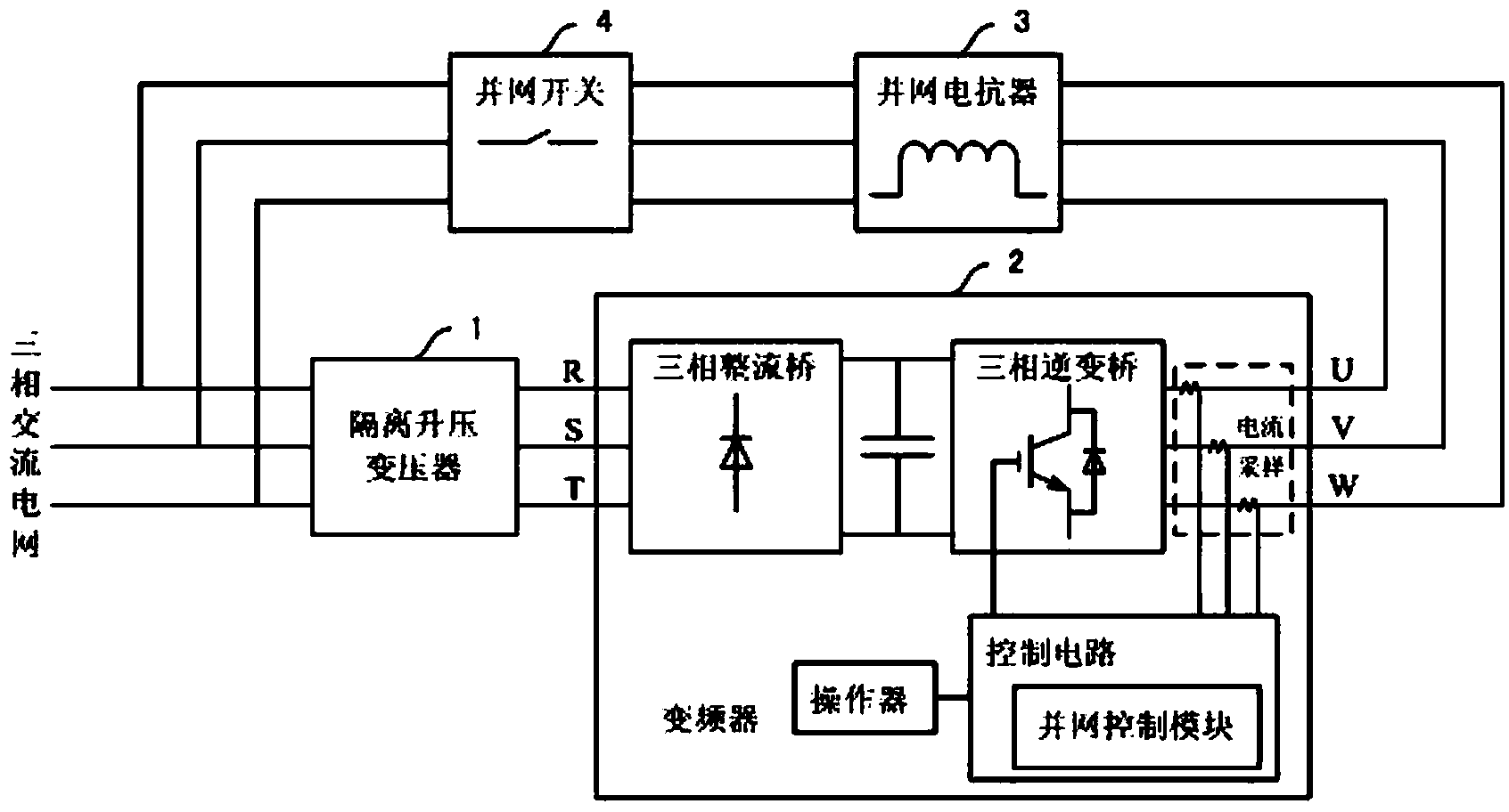
[0046] see Figure 1a , which shows the test system used for the self-circulation aging test of the frequency converter in this example. It can be seen from the figure that the test system is mainly composed of an AC power grid, a step-up transformer 1 , a frequency converter under test 2 , a grid-connected reactor 3 , and a grid-connected switch 4 .

[0047] In this system, the rectification input terminal of the frequency converter 2 under test is connected to the AC grid through the step-up transformer 1, and the AC output terminal is connected to the AC grid through the grid-connected reactor 3 and the grid-connected switch 4 in turn, thus forming a corresponding test environment.

[0048] In this example, the AC grid is a three-phase AC grid, specifically 380V / 50Hz utility power.

[0049] The step-up transformer 1 is an isolation step-up transformer or an auto step-up transformer, specifically a 1:1.15 isolation step-up transformer.

[0050] The grid-connected reactor 3...

example 2

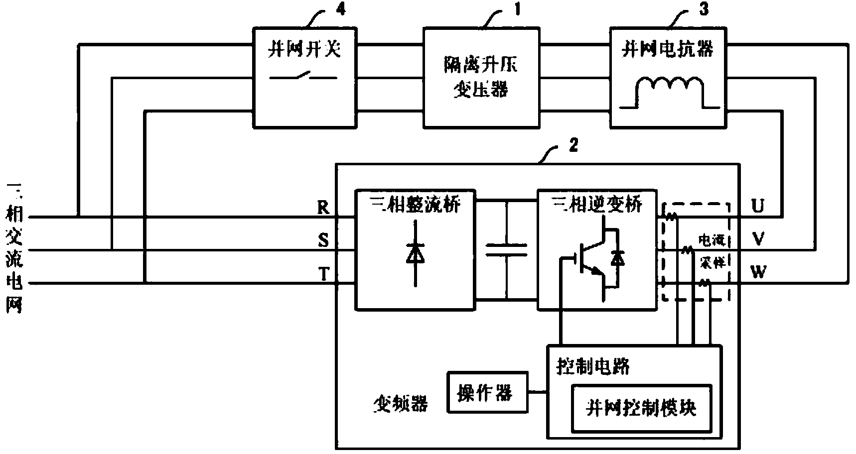
[0058] see Figure 1b , which shows the test system used for the self-circulation aging test of the frequency converter in this example. It can be seen from the figure that the test system is the same as the test system in Example 1. It is mainly composed of an AC power grid, a step-up transformer 1, a frequency converter under test 2, a grid-connected reactor 3, and a grid-connected switch 4.

[0059] In this system, the rectification input terminal of the measured frequency converter 2 is directly connected to the AC grid, while the AC output terminal is connected to the AC grid through the grid-connected reactor 3, step-up transformer 1 and grid-connected switch 4 in turn, thus forming a corresponding test environment.

[0060] Other than that, the rest are the same as the solution in Example 1, and will not be repeated here.

[0061] In this example, the grid-connected control module controls the test environment composed of the AC power grid, step-up transformer 1, test...


PUM


Abstract

The invention discloses a self-circulation aging test system and a test method for a frequency converter. The method comprises the following steps: constructing a test environment by an alternating-current power grid, a boosting transformer, a tested frequency converter, a grid-connected reactor and a grid-connected switch; controlling the alternating-current output end of the tested frequency converter to actively output a detection pulse train before grid-connected running through a grid-connected control module embedded into a tested frequency converter control circuit; identifying the phase sequence and phase of the current network voltage by detecting response current flowing through the grid-connected reactor; performing network voltage tracking and current vector control grid-connected output; feeding grid-connected output electric energy back to the rectification input end of the tested frequency converter through the boosting transformer; controlling the grid-connected output current amplitude to realize self-circulation full-power aging test of the frequency converter. By adopting the self-circulation aging test system and the test method, self-circulation full-power aging test of the frequency converter is realized under the hardware configuration condition of a general frequency converter product. The self-circulation aging test system and the test method have the advantages of easiness in configuration, convenience in operation, real simulation condition, energy saving and high aging efficiency.

Description

technical field [0001] The invention relates to a frequency converter aging test technology, in particular to a frequency converter self-circulation aging test technology. Background technique [0002] The full power aging test is a very important part of the reliability test of the inverter before leaving the factory. For the sake of energy saving, the more full power aging circuits currently used are mainly divided into the following categories: [0003] The Chinese invention patent with the application number CN200710123594.5 provides a resistance and reactance load aging test circuit of a DC-AC inverter, which realizes controlled energy circulation by controlling the reactive power in the bus capacitance and reactance load, but because Most of the output is reactive power, and the input rectifier bridge of the inverter will not be able to provide full power aging conditions, and there is still a large active power loss of the resistive load, and the efficiency is low. ...

Claims


Application Information

Patent Timeline
IPC IPC(8): G01R31/00
Inventor 黄洪剑刘春龙陈安辉石岩峰
Owner SHANGHAI GIE EM
Why Eureka
Try Eureka