Method and device for correcting energy value

A technology of energy value and energy threshold value, applied in the field of photoelectric detection, can solve the problem of image edge resolution reduction, etc., to achieve the effect of eliminating offset

Inactive Publication Date: 2014-09-10
NEUSOFT MEDICAL SYST CO LTD
View PDF4 Cites 26 Cited by
  • Summary
  • Abstract
  • Description
  • Claims
  • Application Information

AI Technical Summary

Problems solved by technology

This will lead to the loss of statistical information of the single event generated by the visible light excited by the gamm

Method used


Image

  • Method and device for correcting energy value
  • Method and device for correcting energy value
  • Method and device for correcting energy value

Examples


Embodiment 1

[0072] Figure 4 It is a flow chart of Embodiment 1 of an energy value correction method in the present invention, the method includes:

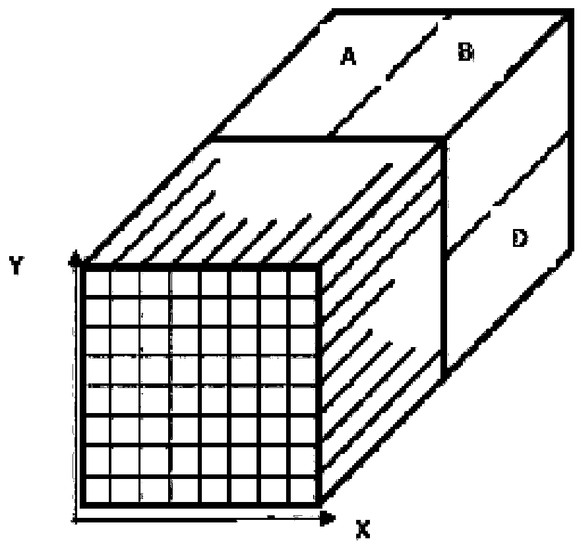
[0073] Step 401: Presetting the energy correction coefficients of each lattice region in the scintillation crystal array.

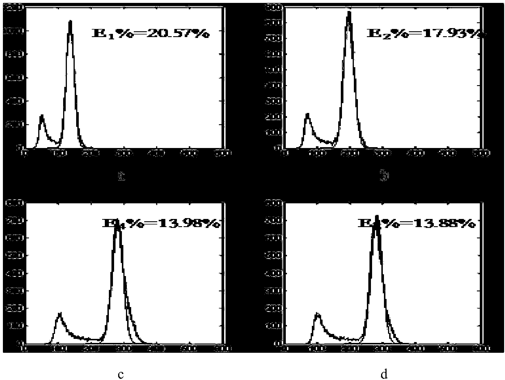
[0074] Each correction coefficient is the ratio of the theoretical energy peak value to the detected energy peak value in the energy value-count value curve obtained by the scintillation crystal array under statistical flood radiation.

[0075] The energy correction coefficient of each lattice area in the scintillation crystal array is used to correct the energy value to be corrected of the single event to be corrected collected by each lattice area. The energy correction coefficient is the ratio of the theoretical energy peak to the detected energy peak in the energy value-count value curve obtained by the scintillation crystal under flood radiation. During specific implementation, an energy correction coefficient ta...

Embodiment 2

[0122] Image 6 It is a flow chart of Embodiment 2 of an energy value correction method of the present invention. Compared with Embodiment 1, Embodiment 2 also includes discarding crystals whose corrected energy values ​​of the single event to be corrected are smaller than the position information of the single event to be corrected. A single event of an energy threshold of a lattice region, the method comprising:

[0123] Step 601: Presetting the energy correction coefficients of each lattice region in the scintillation crystal array.

[0124] An energy correction coefficient is set for each lattice area in the scintillation crystal array, and each correction coefficient is the ratio of the theoretical energy peak value to the detected energy peak value in the energy value-count value curve obtained by the scintillation crystal array under flood radiation.

[0125] Here, it is similar to Embodiment 1, and reference is made to the description of Embodiment 1, and details are ...

Embodiment 3

[0141] Figure 7 It is a structural schematic diagram of Embodiment 3 of an energy value correction device of the present invention. Embodiment 3 is a device corresponding to the method described in Embodiment 1. The device includes:

[0142] The first setting module 701 is configured to preset energy correction coefficients of each lattice region in the scintillation crystal array.

[0143] Figure 8 It is a schematic structural diagram of the first setting module of the present invention, and the first setting module 701 includes:

[0144] The obtaining unit 801 is configured to obtain detection energy values ​​and corresponding detection position information of multiple detection single events under flood radiation.

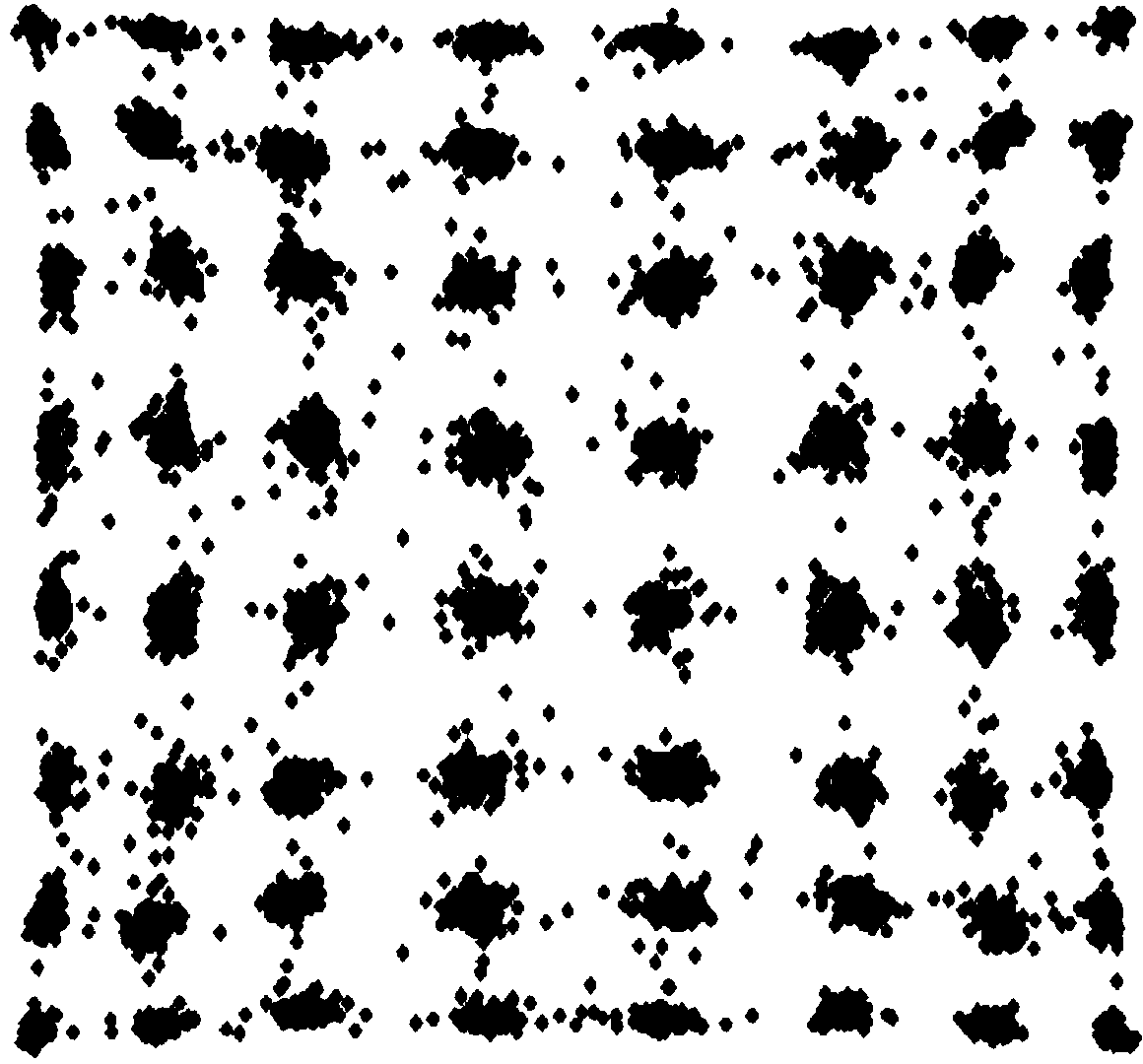
[0145] The first generating unit 802 is configured to generate a two-dimensional scatter diagram of the scintillation crystal array according to the detected energy value and the corresponding detected position information.

[0146] The segmentation unit 80...


PUM


Abstract

The invention provides a method and a device for correcting an energy value. The method comprises the following steps: presetting an energy correction coefficient table; calculating the product of the to-be-corrected energy value of each to-be-corrected single event and the energy correction coefficient of the each to-be-corrected single event to obtain the corrected energy value of the each to-be-corrected single event; counting an energy value-count value curve according to the corrected energy value. The energy correction coefficient is the ratio of a theoretical energy peak value in the energy valve-count value curve obtained by counting an extensive source radiation scintillation crystal array to a detected energy peak, thus the obtained corrected energy value of each to-be-corrected single event deviates towards the theoretical energy value of information about the position of the to-be-corrected single event, thereby eliminating the deviation between an energy value corresponding to a detected count peak value and an energy value corresponding to the theoretical count peak value on the premise of not reducing the statistical information of a scintillation crystal array edge single event.

Description

technical field [0001] The invention relates to the technical field of photoelectric detection, in particular to an energy value correction method and device. Background technique [0002] Positron Emission Tomography-Computed Tomography (PET-CT) equipment and Single-Photon Emission Computed Tomography (Single-Photon Emission Computed Tomography, SPECT) equipment are typical medical imaging equipment today. Among them, the radiation detector, as the core component of PET-CT or SPECT, is mainly used to detect gamma photons produced after the annihilation of positrons and electrons released during the decay of radionuclides. [0003] figure 1 It is a schematic diagram of the structure of a radiation detector in the prior art. After gamma photons are incident on the scintillation crystal array, visible light is excited. Since the positions where the gamma photons are incident on the scintillation crystal array are different, the visible light excited by the scintillation cryst...

Claims


Application Information

Patent Timeline
IPC IPC(8): G01T1/202
Inventor 梁国栋吴国城李楠赵健付长青徐保伟
Owner NEUSOFT MEDICAL SYST CO LTD
Why Eureka
Try Eureka