Parallax grating panel, stereo display and display method using same

A technology of stereoscopic displays and parallax barriers, applied in static indicators, optics, instruments, etc., can solve the problems of users viewing troubles, viewers dizziness, discomfort, inconvenience, etc.

Inactive Publication Date: 2014-09-10
AU OPTRONICS CORP
View PDF7 Cites 11 Cited by
  • Summary
  • Abstract
  • Description
  • Claims
  • Application Information

AI Technical Summary

Problems solved by technology

If the user moves forward or backward out of the viewing area, he may see a stereoscopic image with a high degree of interference (crosstalk), or a phantom or ghost image (pseudoscopy) in which the left and right eye images are reversed, that is, the viewer's left Eyes and right eyes directly enter the left and right eye inversion zone, so viewers are prone to feel dizzy and uncomfortable
Such shortcomings will cause confusion and inconvenience to users when using parallax barrier panels for 3D displays—especially portable devices such as mobile phones, laptops, or tablets.

Method used


Image

  • Parallax grating panel, stereo display and display method using same
  • Parallax grating panel, stereo display and display method using same
  • Parallax grating panel, stereo display and display method using same

Examples


Embodiment Construction

[0053] A number of embodiments of the present invention will be disclosed in the following figures. For the sake of clarity, many practical details will be described together in the following description. It should be understood, however, that these practical details should not be used to limit the invention. That is, in some embodiments of the present invention, these practical details are unnecessary. In addition, for the sake of simplifying the drawings, some existing conventional structures and elements will be shown in a simple and schematic manner in the drawings.

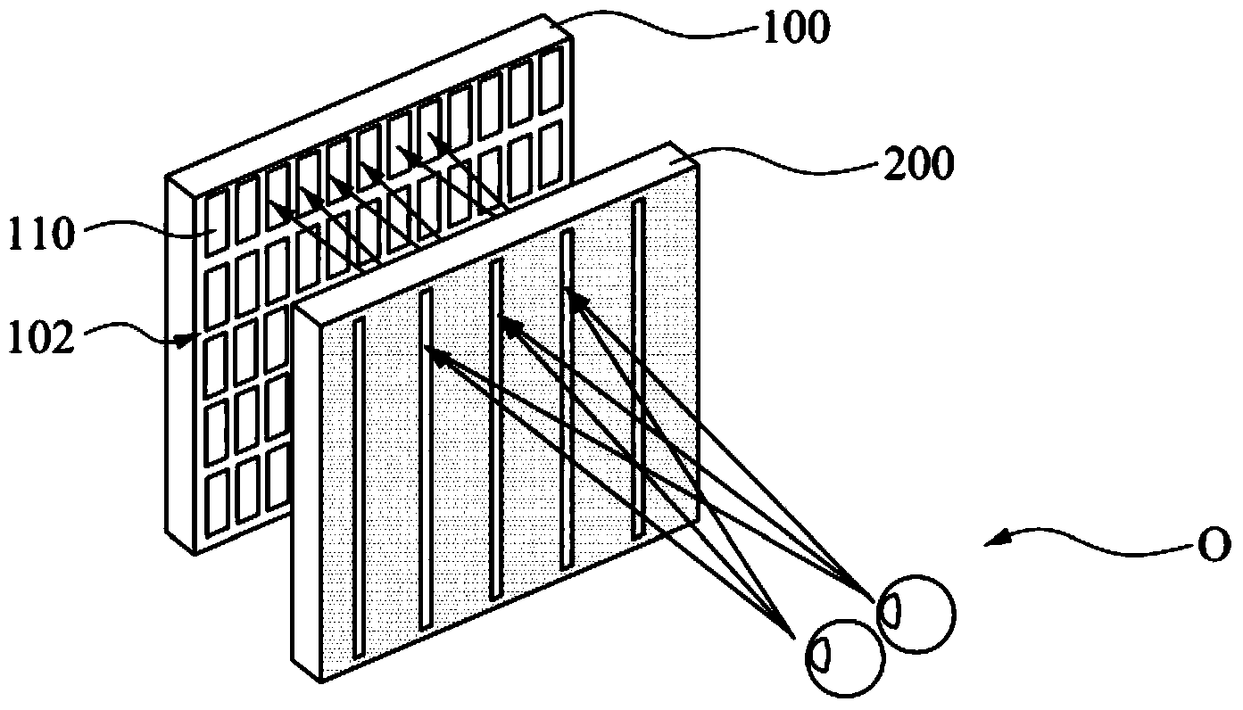
[0054] figure 1 It is a schematic diagram of a stereoscopic display and an observer O according to an embodiment of the present invention. The stereoscopic display includes a flat display panel 100 and a parallax barrier panel 200 . The flat display panel 100 has a display surface 102 . The parallax barrier panel 200 is disposed in front of the display surface 102 of the flat display panel 100 . where fo...


PUM


Abstract

The present invention discloses a parallax grating panel. The parallax grating panel comprises a first substrate, a second substrate, a liquid crystal layer, a plurality of first electrodes, a plurality of auxiliary electrodes, a plurality of second electrodes, and a plurality of second auxiliary electrodes. The liquid crystal layer is disposed between the first substrate and the second substrate. The first main electrodes are disposed between the first substrate and the liquid crystal layer. Each adjacent two first main electrodes have a first pitch P1. The first auxiliary electrodes are disposed between the first substrate and the liquid crystal layer in an alternating manner with the first main electrodes. The second main electrodes are disposed between the second substrate and the liquid crystal layer. Each adjacent two second main electrodes have a second pitch P2. The second auxiliary electrodes are disposed between the second substrate and the liquid crystal layer in an alternating manner with the second main electrodes. The first pitch P1 is smaller than twice of the second pitch P2, and the first pitch P1 is larger than the second pitch P2, namely 2*P2>P1 >P2.

Description

technical field [0001] The present invention relates to a switchable parallax barrier panel and a three-dimensional display, and in particular to a switchable parallax barrier panel and a three-dimensional display with adjustable viewing distance. Background technique [0002] Three-dimensional display uses parallax barrier (Parallax Barrier) technology to add black and white gratings in front of the flat display panel. Because the angles of the left and right eyes viewing the grating are different, the left eye can see part of the pixels, while the right eye can see another part pixels, thereby producing a stereoscopic image effect. The grating can be made, for example, from a liquid crystal panel. [0003] A general liquid crystal panel has a fixed grating width, so the visible area or viewing area of ​​the stereoscopic image is also fixed. If the user moves forward or backward out of the viewing area, he may see a stereoscopic image with a high degree of interference (c...

Claims


Application Information

Patent Timeline
Patent Type & Authority Applications(China)
IPC IPC(8): G02F1/29G02F1/1343G02F1/133G02B27/22
Inventor 廖仁伟
Owner AU OPTRONICS CORP
Why Eureka
Try Eureka