

Light-emitting Device
A technology for light-emitting devices and light-emitting elements, which is applied in the directions of light-emitting materials, semiconductor devices, chemical instruments and methods to achieve the effect of small chromaticity changes
- Summary
- Abstract
- Description
- Claims
- Application Information
AI Technical Summary
Problems solved by technology
Method used
Image

Examples
no. 1 Embodiment approach )
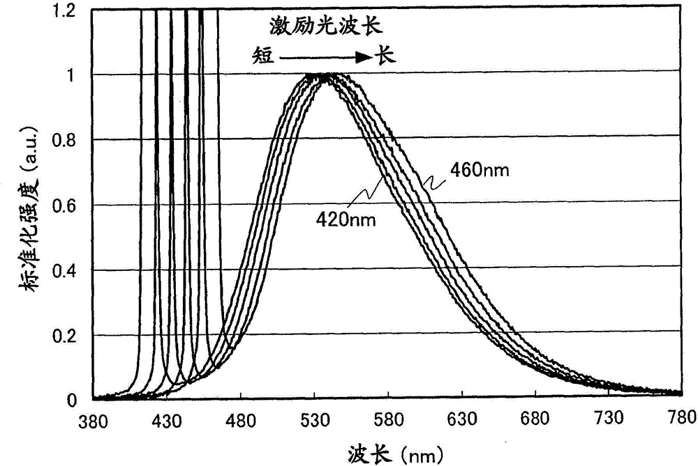
[0021] The light-emitting device of this embodiment includes: a light-emitting element that emits blue excitation light; At least one of a green fluorescent substance that emits green fluorescence excited by blue light, or at least one of a red fluorescent substance that emits red fluorescence excited by blue light. The peak wavelength of the fluorescence is more than 520nm and less than 660nm. In the case of wavelength shift, the peak wavelength of fluorescence shifts in the same direction.
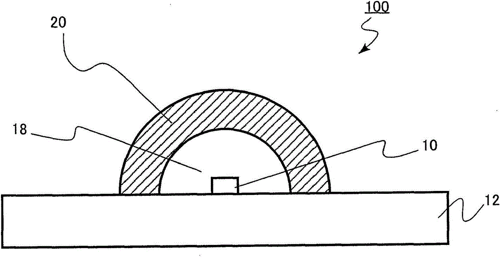
[0022] figure 1 It is a schematic cross-sectional view of the light emitting device of the embodiment. In the following, a white light-emitting device that emits daytime white (color temperature 5000K) by mixing the blue excitation light emitted by the light-emitting element with the yellow fluorescence emitted by the yellow phosphor as an example will be described below. illustrate.
[0023] The light emitting device 100 includes a mounting substrate 12 having a flat surface on which...
no. 2 Embodiment approach )
[0058] The light-emitting device of this embodiment includes: a light-emitting element that emits blue excitation light; a wavelength shift phosphor that is formed on the light-emitting element and is a yellow phosphor that is excited by the excitation light to emit yellow fluorescence And at least one of the green phosphor that emits green fluorescence, or the red phosphor that is excited by the excitation light to emit red fluorescence, the peak wavelength of the fluorescence is more than 520nm and less than 660nm, and the peak wavelength of the excitation light is shifted. Under the circumstances, the peak wavelength of the fluorescence shifts to the same direction; and the dimming mechanism changes the luminous intensity of the light-emitting element.
[0059] The light emitting device of this embodiment is the same as that of the first embodiment except that it includes a dimming mechanism. Therefore, the description of the content overlapping with the first embodiment wi...
Embodiment )
[0067] As a yellow-green / yellow phosphor, (Sr 0.98 Ce 0.02 ) 2 al 3 Si 7 o 1 N 13 , used as a red phosphor as a sialon phosphor (Sr 0.98 Eu 0.02 ) 2 al 3 Si 7 o 1 N 13 , to disperse a substance obtained by mixing them in a weight ratio of 5:1 into the resin. Then, a resin obtained by dispersing yellow-green / yellow phosphors and red phosphors was coated on the sapphire substrate, and the resin was cured by standing in an environment of 150° C. for 30 minutes. In this way, the phosphor layer was formed on the substrate. A light-emitting device that generates white light by adjusting the chromaticity by adjusting the coating amount of the resin was obtained.
[0068] In addition, regarding (Sr 0.98 Ce 0.02 ) 2 al 3 Si 7 o 1 N 13 , the peak wavelength of fluorescence is not less than 520 nm and less than 600 nm, and when the peak wavelength of excitation light shifts, the peak wavelength of fluorescence shifts in the same direction.
[0069] Figure 5 It is ...
PUM
| Property | Measurement | Unit |
|---|---|---|
| Peak wavelength | aaaaa | aaaaa |
| Wavelength | aaaaa | aaaaa |
| Peak wavelength | aaaaa | aaaaa |
Abstract
Description
Claims
Application Information