Eureka AIR delivers breakthrough ideas for toughest innovation challenges, trusted by R&D personnel around the world.

Coreless type megawatt superconducting motor system

A superconducting motor, ironless technology, applied in the usage of superconductor elements, electrical components, electromechanical devices, etc., can solve problems such as affecting the normal operation of the system, increasing the quality of the system, discounting the excitation effect, etc., to solve the mechanical stress and support. Protection problems, ensuring low temperature environment, the effect of good mechanical properties

Inactive Publication Date: 2014-09-10
UNIV OF ELECTRONIC SCI & TECH OF CHINA
View PDF4 Cites 8 Cited by
  • Summary
  • Abstract
  • Description
  • Claims
  • Application Information

AI Technical Summary

Problems solved by technology

However, the iron core structure also has its negative effects, such as the existence of magnetic saturation, which affects the linear increase of the air gap magnetic density, and at the same time greatly increases the quality of the system, increasing the difficulty of transportation and assembly
Theoretically, adopting a hollow structure can well solve the above-mentioned problems caused by the iron core structure, but since the iron core is removed, not only the excitation effect is greatly reduced, but also the centrifugal force and Lorentz force will directly act on the superstructure. On the guiding excitation coil, especially for the track-type excitation coils that are structurally independent, the effect is particularly obvious. In severe cases, such as a short-circuit fault, the superconducting material will be deformed or even broken, which will seriously affect the normal operation of the entire system.

Method used


Image

  • Coreless type megawatt superconducting motor system
  • Coreless type megawatt superconducting motor system
  • Coreless type megawatt superconducting motor system

Examples


Embodiment 1

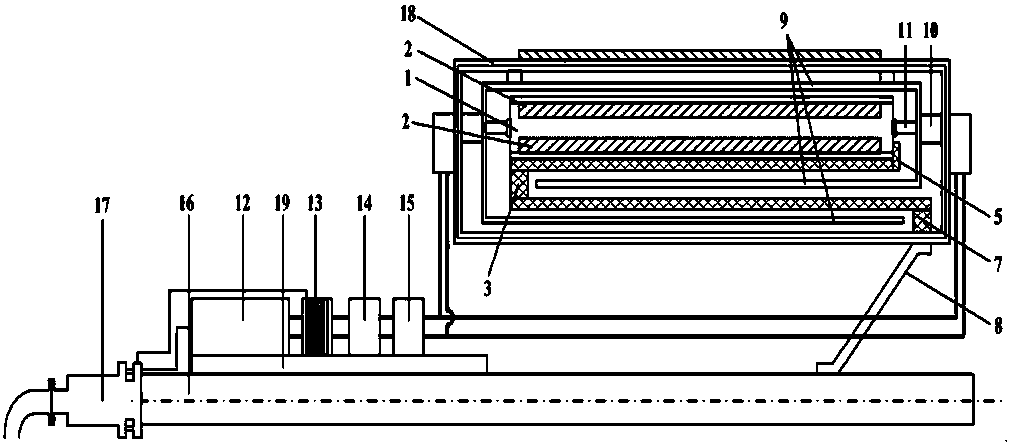
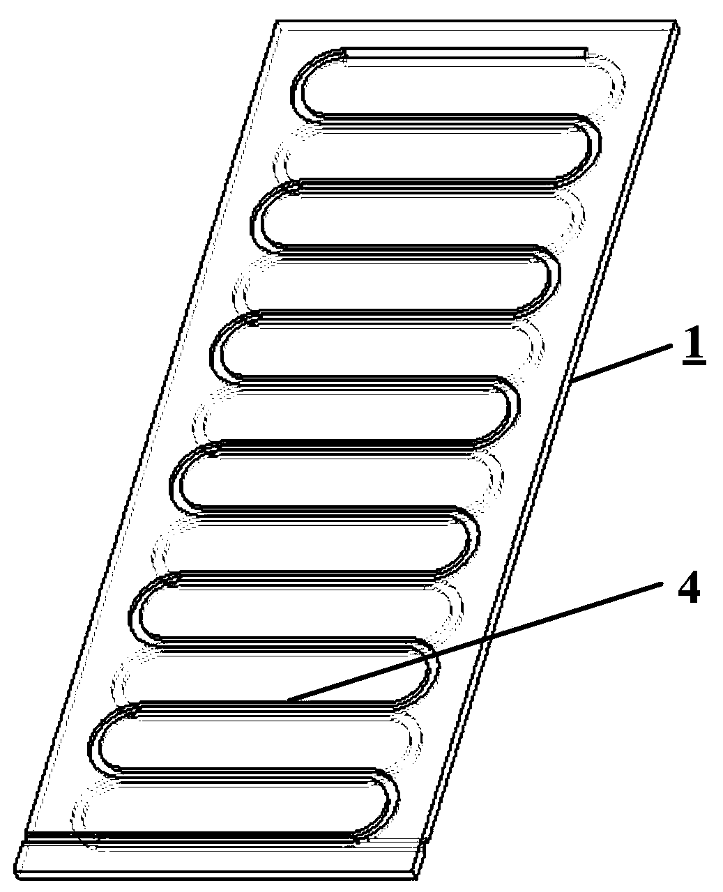
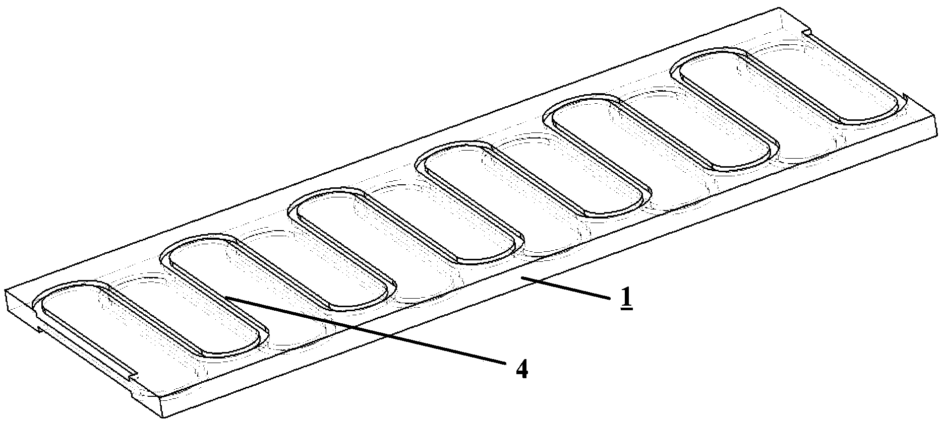
[0036] Such as figure 1 , figure 2 , image 3 , Figure 4 , Figure 5 , Image 6 , Figure 7 shown. Build an ironless megawatt-class superconducting motor system, including a conventional stator, a superconducting rotor with an ironless structure, and a low-temperature refrigeration device; the axial length of the rotor is 1.5m, and the rotor diameter is 1.2m. Specific structure: The stator is a copper armature winding with a double-layer structure. The rotor includes a bobbin 1 , a superconducting excitation coil 2 wound on the bobbin 1 with YBCO high temperature superconducting tape, and a torque tube 3 connected to the bobbin 1 . Both the upper and lower surfaces of a bobbin 1 are provided with grooves in a convoluted U-shaped structure. The groove structures on the upper and lower surfaces are 180° out of phase and connected to each other; the YBCO superconducting strip starts to wind from the beginning of the upper surface groove system, wound to the end of the ...

Embodiment 2

[0041] The parts that are the same as those in Embodiment 1 will not be described again, except that the axial length of the rotor is 2.0 m, and the diameter of the rotor is 1.5 m. Using low temperature superconducting material MgB 2 The wire is wound on the bobbin 1 to form a superconducting excitation coil 2 . The grooves on the upper and lower surfaces of the bobbin 1 are structurally independent of each other, MgB 2 The wires are respectively wound on the upper and lower surfaces of the bobbin 1 , and finally the superconducting excitation coil 2 wound on the upper surface of the bobbin 1 and the superconducting exciting coil 2 wound on the lower surface of the bobbin 1 are independent of each other.

Embodiment 3

[0043] The same places as in Example 1 will not be repeated, and the difference is that: the YBCO high-temperature superconducting tape 22, the BSCCO high-temperature superconducting tape 21 and the MgB 2 The low-temperature superconducting wire 20 is connected in parallel with three kinds of superconducting materials, wound on the bobbin 1 to form a superconducting excitation coil 2, and the three kinds of superconducting materials are arranged in sequence along the direction close to the bobbin 1 as MgB 2 Low-temperature superconducting wire 20, BSCCO high-temperature superconducting tape 21 and YBCO high-temperature superconducting tape 22 (the specific structure is as follows Figure 8 shown), that is, the farthest from the bobbin 1 is MgB 2 The low-temperature superconducting wire 20, and the YBCO high-temperature superconducting strip 22 closest to the bobbin 1; the superconducting excitation coil 2 wound on the upper and lower surfaces of the bobbin 1 is formed by contin...


PUM


Abstract

The invention discloses a coreless type megawatt superconducting motor system. The coreless type megawatt superconducting motor system comprises a superconducting rotor of coreless structure, wherein the superconducting rotor of the coreless structure comprises a coil skeleton, superconducting excitation coils and a torque tube connected with the coil skeleton, the superconducting energizing coils are wound around the upper surface and the lower surface of the coil skeleton and wound in convolution U structure, each two adjacent effective excitation edges are parallel to each other and respectively form a positive pole and a negative pole in a pair of magnetic poles, the effective excitation edges of the superconducting energizing coil wound around the upper surface of the coil skeleton and the effective excitation edges of the superconducting energizing coil wound around the lower surface of the coil skeleton are symmetric around the coil skeleton, and exciting current directions of each two effective excitation edges which are symmetric around the coil skeleton are the same. Compared with the prior art, the coreless type megawatt superconducting motor system has better excitation effects and mechanical properties than a track type excitation coil through structure design of the superconducting excitation coils, the support skeleton of the superconducting excitation coils and the torque tube, and can commendably solve the problems of excitation effect reduction, mechanical stress change and support protection reduction of the superconducting excitation coils, generated after iron cores are removed.

Description

technical field [0001] The invention relates to an ironless megawatt class superconducting motor system with a convoluted U-shaped structure superconducting excitation coil. Background technique [0002] The biggest advantages of superconducting motors are high efficiency, small size and light weight. For large motor systems of more than ten megawatts, such as wind turbines and ship propulsion motors, an iron core structure is usually used on the rotor to constrain the magnetic circuit, strengthen the magnetic field, and at the same time support and protect the superconducting excitation coil. However, the iron core structure also has its negative effects, such as the existence of magnetic saturation, which affects the linear increase of the air gap magnetic density, and at the same time greatly increases the quality of the system and increases the difficulty of transportation and assembly. Theoretically, adopting a hollow structure can well solve the above-mentioned proble...

Claims


Application Information

Patent Timeline
IPC IPC(8): H02K55/00H02K1/28
CPCY02E40/62Y02E40/60
Inventor 金建勋姜在强
Owner UNIV OF ELECTRONIC SCI & TECH OF CHINA
Why Eureka
Eureka Blog
Learn More