
In-process compensation of machining operation and machine arrangement

A machine and process technology, applied in the direction of metal processing machinery parts, metal processing, metal processing equipment, etc., can solve the problems of increasing the contour error of processing parts, hindering production efficiency, final quality and performance damage, and achieve the effect of improving precision

Inactive Publication Date: 2014-09-10
AB SKF
View PDF7 Cites 14 Cited by
  • Summary
  • Abstract
  • Description
  • Claims
  • Application Information

AI Technical Summary

Problems solved by technology

[0004] Machining operations, however, involve highly complex interactions between the cutting tool and the machined surface of the workpiece, which hinder the precision and performance of shaped components during the manufacturing process
For example, initial workpiece deformations (e.g. from hardening processes) as well as initial high levels of surface roughness and dimensional inaccuracies of the machined surfaces to be treated have a negative influence on the machining results
Furthermore, substantially random and / or uncontrollable turning processes associated with the cutting tool, such as chipping, fracture, wear, tooling, etc., affect the final cut, e.g. by increasing the contour error of the machined part
This results in compromised final quality and performance of the part and hampers productivity

Method used


Image

  • In-process compensation of machining operation and machine arrangement
  • In-process compensation of machining operation and machine arrangement
  • In-process compensation of machining operation and machine arrangement

Examples


Embodiment Construction

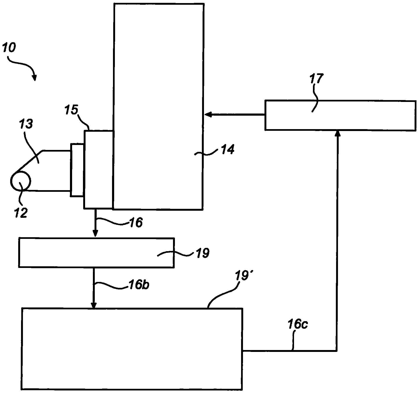
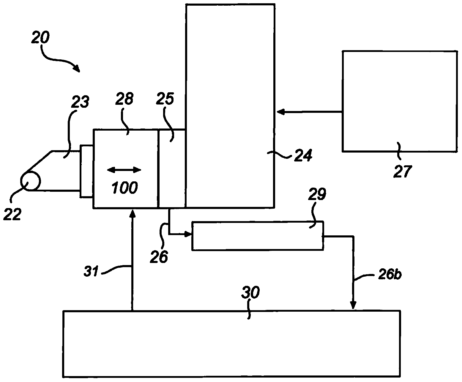
[0050] Hereinafter, the present invention will be described more fully hereinafter with reference to the accompanying drawings, in which exemplary embodiments of the invention are shown. However, this invention may be embodied in many different forms and should not be construed as limited to the embodiments set forth herein; rather, these embodiments are intended to be thorough and complete. Like reference symbols refer to like elements throughout. The drawings are schematic only and not drawn true to scale.

[0051] exist figure 1 and 2 In , schematic diagrams of two exemplary machine arrangements 10 and 20 for performing machining operations according to the invention are shown. The machine arrangements 10 and 20 each include respective cutting tools 12 and 22, such as carbide, CBN, ceramic or non-ceramic inserts, and respective tool holders 13 and 23 for supporting the cutting tools during machining operations.

[0052] refer to figure 1 , the tool holder 13 is firmly ...


PUM


Abstract

The present invention relates to a method for performing in-process compensating a machining operation on a workpiece, wherein the compensation process comprises generating a control signal representative of magnitude of a contact force exerted on a cutting tool in a normal direction in relation to a machining surface of the workpiece, determining a compensation parameter value based on the control signal, and compensating the machining operation based on the compensation parameter value. The present invention also relates to corresponding machine arrangement for performing machining operation on a workpiece, such as a hard turning process.

Description

technical field [0001] The invention relates to a method and a machine arrangement for performing a machining operation on a workpiece, wherein said machining operation comprises subjecting the machined surface of the workpiece by means of a cutting tool and by providing a relative rotational movement between said workpiece and cutting tool and relative translational motion physically removes material from the workpiece. For example, the invention can be used for turning, hard turning and boring (internal turning) of eg metal or ceramic components, eg using lathes or automatic lathes, based on manual, semi-automatic or automatic machining operations. For example, machining operations may be based on CNC (Computer Numerical Control), wherein commands are communicated to, for example, a machine tool arranged to perform machining operations based on CNC parameters. Background technique [0002] Various high-performance and high-quality metal, steel or ceramic components, such ...

Claims


Application Information

Patent Timeline
Patent Type & Authority Applications(China)
IPC IPC(8): B23Q15/12B23B25/06B23Q15/007
CPCG05B19/404G05B2219/49169B23B2215/12B23B2228/24G05B2219/49168G05B2219/49186G05B2219/49099G05B2219/37374G05B2219/49184
Inventor J.卡明斯基S.霍格纳斯O.A.内古姆博
Owner AB SKF
Learn More