Evaporator burner for a mobile heating device

A technology of heating device and vaporizer, which is applied in the field of vaporization burner, can solve the problems of deteriorating combustion characteristics, and achieve the effects of good combustion characteristics, strong cooling and simple structure

Active Publication Date: 2014-09-10
WEBASTO AG
View PDF4 Cites 3 Cited by
  • Summary
  • Abstract
  • Description
  • Claims
  • Application Information

AI Technical Summary

Problems solved by technology

Especially in mobile heating units with vaporization burners, there is a tendency to deteriorate the combustion characteristics when these mobile heating units are operated in the lower areas of the respective heating power coverage

Method used


Image

  • Evaporator burner for a mobile heating device
  • Evaporator burner for a mobile heating device
  • Evaporator burner for a mobile heating device

Examples


Embodiment Construction

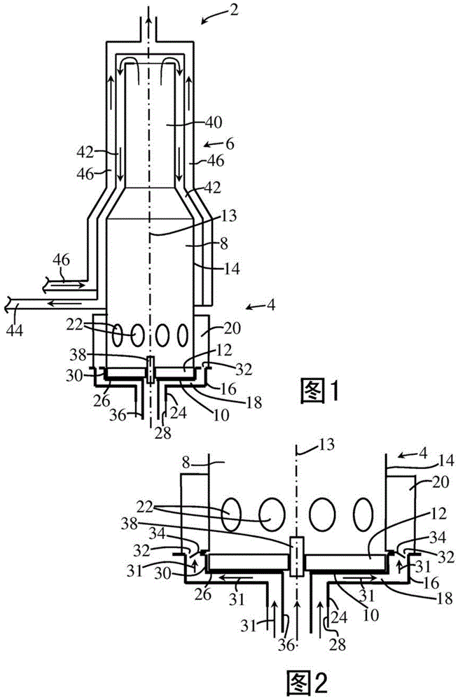
[0030] exist figure 1 In , a mobile fuel-operated heating device 2 forming a parking heater for a land vehicle is schematically shown. In the following, reference is made in particular to those parts which have a certain relation to the present invention. The heating device 2 includes a vaporization burner 4 and a heat exchanger 6 . Among other components, the vaporization burner 4 comprises a combustion chamber 8 , a vaporizer receptacle 10 and a vaporizer element 12 for vaporization of liquid fuel. The combustion chamber 8 , the evaporator receptacle 10 and the evaporator element 12 are substantially circular and comprise a common axis of rotational symmetry 13 .

[0031] In the circumferential direction, the combustion chamber 8 is delimited by a circumferential combustion chamber wall 14 . On the front side of the fuel supply area, the combustion chamber 8 is delimited by a carburetor receptacle 10 . The evaporator element 12 is accommodated in the side of the evaporat...


PUM


Abstract

The invention relates to an evaporator burner (4) for a mobile heating device (2), comprising a combustion chamber (8), an evaporator receptacle (10), and an evaporator element (12) for evaporating liquid fuel. Said evaporator element (12) is received in the evaporator receptacle (10) on the side facing the combustion chamber (8). On the side of the evaporator receptacle (10) facing away from the combustion chamber (8), the evaporator burner (4) has at least one combustion air guide element (16), which is arranged in such a way that a combustion air flow path extending at least along a section of the bottom wall (26) of the evaporator receptacle (10) is formed between the combustion air guide element (16) and a bottom wall (26) of the evaporator receptacle (10).

Description

technical field [0001] The invention relates to a gasification burner for a mobile heating device according to the preamble of claim 1 . Background technique [0002] In mobile heating installations, especially in parking heaters and / or auxiliary heaters for vehicles such as, for example, engine-driven land vehicles, vaporization burners are used. Such a vaporizing burner comprises a vaporizer element formed of a structure capable of being flowed through, interspersed with a large number of pores to obtain good vaporization of the liquid fuel. Furthermore, the gasification burner comprises a combustion chamber for the flaming combustion of the (vaporized) fuel and combustion air. A combustion chamber is formed axially adjacent to the carburetor and is generally at least partially bounded by a circumferential combustion chamber wall, also referred to as a combustion duct. [0003] In operation, liquid fuel is supplied to the carburetor element. The capillary effect of the ...

Claims


Application Information

Patent Timeline
IPC IPC(8): F23C7/00F23C7/04F23C7/06F23D3/40
CPCB60H1/2203F23D5/18F23D3/18F23D2900/05002F23D3/40F23C7/004F23C7/06F23C7/04
Inventor D·乔兹诺维克B·迈尔A·温特V·戴尔
Owner WEBASTO AG
Why Eureka
Try Eureka