X-ray recording system for differential phase contrast imaging of an examination object by way of phase stepping

A phase-contrast imaging and shooting system technology, which is applied in the fields of radiological diagnostic instruments, medical science, computer tomography scanners, etc., can solve the problems of imaging failure, inability to use high-precision optical bench, wrong imaging, etc., to achieve Guaranteed geometric accuracy, real-time measurement and correction effect

Inactive Publication Date: 2014-09-17
SIEMENS AG
View PDF6 Cites 3 Cited by
  • Summary
  • Abstract
  • Description
  • Claims
  • Application Information

AI Technical Summary

Problems solved by technology

Changes in the distance between components in other positional orientations as well as tilting, rotation, etc. required to produce an image can lead to erroneous imaging or even complete failure of the imaging
[0027] For medical applications where high-precision optical benches cannot be used, and here in particular for potential applications in angiography or surgery where an X-ray system with a C-bow arm can be used, as for example according to figure 1 explained by figure 1 In general, continuously changing forces (gravity, centrifugal, etc.) and the corresponding components, so that the conventional mechanisms used today are not adequate, since inaccuracies of up to a few hundred μm or more can occur here

Method used


Image

  • X-ray recording system for differential phase contrast imaging of an examination object by way of phase stepping
  • X-ray recording system for differential phase contrast imaging of an examination object by way of phase stepping
  • X-ray recording system for differential phase contrast imaging of an examination object by way of phase stepping

Examples


Embodiment Construction

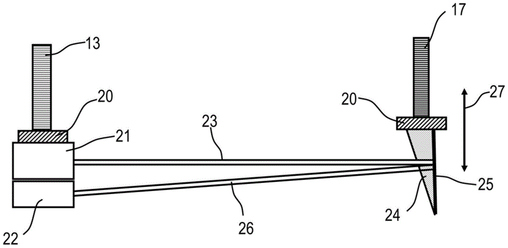
[0057] image 3 depicts for example two gratings G 0 and G 1 The principle of the detection of the height adjustment of the components. The absorption grating 13 and the phase grating 17 are held by the connecting portion 20 . The absorption grating 13 and the laser 21 are correspondingly arranged for a photosensor such as a photodiode 22 . The laser 21 emits a laser beam 23 which reaches a translucent wedge 24 assigned to the phase grating 17 and passes through the wedge 24 attenuated. On the rear side of the translucent wedge 24 is mounted a rear side mirror 25 which projects the reflected laser beam 26 further weakened by the translucent wedge 24 onto the photodiode 22 . Depending on the relative movement 27 , for example due to shocks, the reflected laser beam 26 is attenuated relative to the emitted laser beam 23 so that the output signal of the photodiode 22 describes the degree to which the position of the phase grating 17 is shifted.

[0058] exist Figure 4 For ...


PUM


Abstract

An x-ray recording system is for differential phase contrast imaging of an examination object (6) via phase stepping. In an embodiment, the x-ray recording system includes at least one x-ray emitter (3) for generating quasi coherent x-ray radiation; an x-ray image detector (4) with pixels arranged in a matrix; a defraction or phase grating (17) arranged between the examination object (6) and the x-ray image detector (4); and an analyzer grating (18) assigned to the phase grating (17), wherein the x-ray emitter (3) the x-ray image detector (4), the phase grating (17) and the analyzer grating (18) for the phase contrast imaging form components (32, K1 to Kn) in an arrangement. According to an embodiment, at least one measuring apparatus (34) for determining deviations in the geometric ratios of the components relative to one another from the geometry target, an analysis unit (35, 40) for evaluating the measured deviations, a computing unit (36, 41) for determining correction values and at least one correction device (37, 37, 42, 46) for setting the geometric ratios of the components (32, K1 to Kn) are included.

Description

technical field [0001] The invention relates to an x-ray imaging system for differential phase-contrast imaging of an examination object by means of phase stepping, said system having at least one x-ray emitter for generating quasi-coherent x-ray radiation, with an array arranged in a matrix The X-ray image detector of the pixels, the diffraction grating or phase grating arranged between the inspection object and the X-ray image detector, and the analyzer grating correspondingly equipped for the phase grating, wherein the X-ray radiator, X-ray image detection The detector, phase grating and analyzer grating form the critical components for phase-contrast imaging within a given device. Background technique [0002] Differential phase-contrast imaging is an imaging method that has recently received much attention, especially in Talbert-Law interferometer applications. It is thus described, for example, in the publication F. Pfeiffer et al. [1], "Hard X-ray dark-field imaging ...

Claims


Application Information

Patent Timeline
Patent Type & Authority Applications(China)
IPC IPC(8): A61B6/00A61B6/03
CPCA61B6/4458A61B6/4464A61B6/484A61B6/588A61B6/587A61B6/4441
Inventor M.斯帕恩
Owner SIEMENS AG
Why Eureka
Try Eureka