Temperature control catheter with temperature sensor

A temperature sensor and temperature sensor technology, applied in the field of medical devices, can solve the problems of long induction process, difficult control of body surface cooling temperature, easy excessive cooling or heating, etc., so as to increase the contact surface and reduce the risk of complications and death. , the effect of rapidly changing the temperature

Inactive Publication Date: 2014-09-17
CHENGDU JIAYI TECH
View PDF5 Cites 2 Cited by
  • Summary
  • Abstract
  • Description
  • Claims
  • Application Information

AI Technical Summary

Problems solved by technology

[0002] At present, the method of cooling or heating the human body in my country basically adopts the method of body surface temperature regulation, such as using ice packs or ice blankets to cool down. Body surface cooling can achieve the purpose of cooling to a certain extent, but the existing body surface cooling temperature is not easy to control. The operation process is cumbersome, the induction process is long, and it is easy to excessively cool down or heat up
Excessive cooling not only fails to achieve the therapeutic effect, but also easily leads to corresponding complications of patients, and even increases the risk of death

Method used


Image

  • Temperature control catheter with temperature sensor
  • Temperature control catheter with temperature sensor
  • Temperature control catheter with temperature sensor

Examples


Embodiment 1

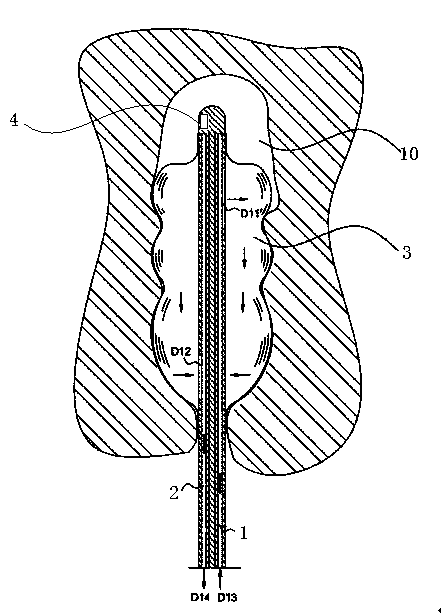
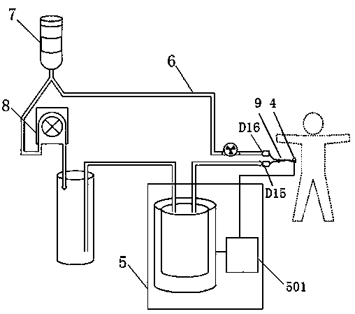
[0018] as attached figure 1 , attached figure 2 As shown, the temperature control catheter with a temperature sensor in this embodiment includes a water inlet channel 1, a water return channel 2 and a balloon 3, wherein the water inlet channel 1 includes a distal water inlet D11, and the water return channel 2 includes a remote water inlet D11. The end return water port D12, the balloon 3 is located at the far end of the catheter, the openings of the distal water inlet D11 and the distal return water port D12 are located in the balloon 3, the water inlet channel 1 also includes a proximal water injection port D13, and the return water chamber The channel 2 also includes a proximal water outlet D14, and a temperature sensor 4 is provided at the front end of the catheter. The proximal water injection port D13 and the water outlet D14 are respectively connected with the water outlet D15 and the water inlet D16 of the heat regulating device; the temperature sensor 4 is connecte...

Embodiment 2

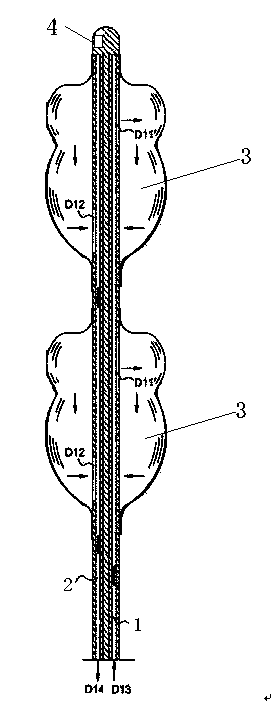
[0022] as attached image 3 As shown, the structure of this embodiment is the same as that of Embodiment 1, the difference is that the temperature control catheter of this embodiment contains two balloons 3, and the two balloons are sequentially arranged at intervals, and each balloon 3 is connected to the water inlet channel 1 It communicates with the backwater channel 2. The two balloons 3 further increase the contact surface for heat exchange, which helps to quickly change the temperature in the body.


PUM


Abstract

The invention relates to the field of a medical appliance, in particular to a temperature control catheter with a temperature sensor. The temperature control catheter with the temperature sensor comprises a water inlet orifice, a water return orifice and a saccule, wherein the water inlet orifice comprises a far end water inlet, the water return orifice comprises a far end water return opening, the saccule is positioned at the far end of the catheter, openings of the far end water inlet and the far end water return opening are positioned in the saccule, the water inlet orifice also comprises a near end water filling opening, the water return orifice also comprises a near end water outlet, and the front end of the catheter is provided with the temperature sensor. The temperature control catheter has the advantages that the saccule is utilized for continuously carrying out heat exchange with the blood in the postcava of a patient, and the goal of controlling the human body temperature is achieved; the blood temperature of the patient can be detected in real time through the temperature sensor, and the temperature of heat exchange fluid filled into the saccule can be regulated in time; when the temperature control catheter is provided with a plurality of saccules, the heat exchange contact area can be further increased, and the temperature in the body can be fast changed.

Description

technical field [0001] The invention relates to the field of medical equipment, in particular to a temperature-controlled catheter with a temperature sensor. Background technique [0002] At present, the method of cooling or heating the human body in my country basically adopts the method of body surface temperature regulation, such as using ice packs or ice blankets to cool down. Body surface cooling can achieve the purpose of cooling to a certain extent, but the existing body surface cooling temperature is not easy to control. The operation process is cumbersome, the induction process is long, and it is easy to excessively cool down or heat up. Excessive cooling not only fails to achieve the therapeutic effect, but also easily leads to corresponding complications of patients, and even increases the risk of death. Contents of the invention [0003] The purpose of the present invention is to overcome the above-mentioned deficiencies of the prior art, and provide a temperat...

Claims


Application Information

Patent Timeline
Patent Type & Authority Applications(China)
IPC IPC(8): A61F7/12
Inventor 缪海昕
Owner CHENGDU JIAYI TECH
Why Eureka
Try Eureka