Device for assisting in laser drilling with rotating electric field

A technology that assists lasers and electromagnetic fields. It is used in laser welding equipment, welding/welding/cutting items, manufacturing tools, etc. It can solve the problem of not being able to increase the unit plasma energy, and achieve the effect of ensuring processing stability and convenient operation.

Active Publication Date: 2014-09-17
JIANGSU UNIV
View PDF7 Cites 12 Cited by
  • Summary
  • Abstract
  • Description
  • Claims
  • Application Information

AI Technical Summary

Problems solved by technology

However, the methods involved in the above two devices only change the direction of motion of the plasma, and cannot increase the energy of the unit plasma.

Method used


Image

  • Device for assisting in laser drilling with rotating electric field
  • Device for assisting in laser drilling with rotating electric field
  • Device for assisting in laser drilling with rotating electric field

Examples


Embodiment 1

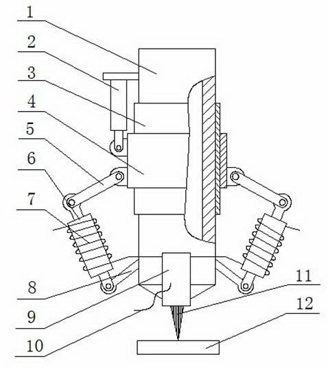
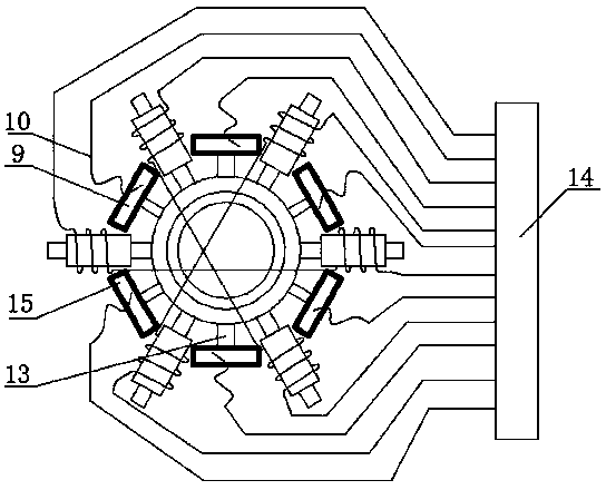
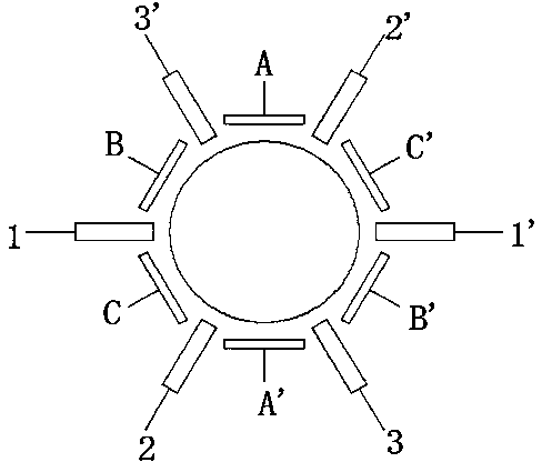
[0035] A device for rotating electromagnetic field assisted laser drilling using the present invention such as figure 1 and figure 2 The shown includes a laser head 1 and a rotating electromagnetic field generating device. The rotating electromagnetic field generating device is installed on the laser head 1 and is coaxial with the laser head; the rotating electromagnetic field generating device includes a hydraulic cylinder 2, a guide post 3, a guide sleeve 4, and three pairs of Connecting rod 5, three pairs of iron cores 6, three pairs of coil windings 7, three pairs of support rods 8, three pairs of electric boards 9, wires 10, controller 14 and three pairs of electric board supports 13; three pairs of iron cores 6 along the laser The head 1 is evenly distributed in the circumferential direction. The upper and lower ends of the iron core 6 are respectively hinged with one end of the connecting rod 5 and the support rod 8 fastened to the lower end of the laser head 1. The o...

Embodiment 2

[0049] see figure 1 and figure 2 , the device of this embodiment is the same as that of Embodiment 1, except that two pairs of connecting rods 5, two pairs of iron cores 6, two pairs of coil windings 7, two pairs of support rods 8, two pairs of electric plates 9 and two pairs of The electric plate supports 13, and the number of turns of the coil winding 7 is 600 turns.

[0050] The controller 14 adjusts the excitation current to 1.8A, the voltage between the plates to 60V, and the current-voltage change frequency to 100Hz, so that the rotating electromagnetic field generating device generates a rotating electromagnetic field with a certain intensity and frequency; at the same time, by adjusting the extension length of the hydraulic cylinder 2 , to drive the connecting rod 5 and the iron core 6 to rotate, so that the angle between the two opposing coil windings 7 is 120°.

Embodiment 3

[0052] see figure 1 and figure 2 , the device of this embodiment is the same as that of Embodiment 1, except that eight pairs of connecting rods 5, eight pairs of iron cores 6, eight pairs of coil windings 7, eight pairs of support rods 8, eight pairs of electric plates 9 and eight pairs of The electric plate supports 13, and the number of turns of the coil winding 7 is 700 turns.

[0053] The controller 14 adjusts the excitation current to 2A, the voltage between the plates to 100V, and the current-voltage change frequency to 200Hz, so that the rotating electromagnetic field generating device generates a rotating electromagnetic field with a certain intensity and frequency; at the same time, by adjusting the extension length of the hydraulic cylinder 2, Drive the connecting rod 5 and the iron core 6 to rotate, so that the included angle between the two opposing coil windings 7 is 90°.


PUM


Abstract

The invention discloses a device for assisting in laser drilling with a rotating electric field. N pairs of iron cores are distributed along the circumference of a laser head uniformly at intervals, the upper and lower ends of each iron core are respectively hinged to a connecting rod and a supporting rod fastened at the lower end of the laser head, the other end of each connecting rod is hinged to a guide sleeve, the guide sleeve sleeves the outer wall of a guide pillar coaxially fixed on the laser head, the upper end of the guide sleeve is connected with a hydraulic cylinder fixed on the upper end of the laser head, the guide sleeve can move up and down along the guide pillar, N pairs of coil windings respectively sleeve the N pairs of iron cores and are connected with a controller, N pairs of electroplates are respectively fixed on the lower end of the laser head through N pairs of electroplate supports, the N pairs of electroplates are located on the same plane and each electroplate is located at the central position of an included angle formed by two corresponding adjacent coil windings, and the electroplates of which the surfaces are coated with insulated layers are connected with the controller through conducting wires. According to the device, the drilling efficiency can be improved, and the device is applicable to laser drilling processing on all materials.

Description

technical field [0001] The invention relates to the field of laser processing, in particular to a device that uses a rotating electromagnetic field to assist laser light drilling. technical background [0002] With the continuous development of micro-electromechanical technology (MEMS) and the miniaturization and lightweight design of traditional products, people have higher and higher requirements for micro-hole processing technology. Traditional machining methods have been unable to meet the processing requirements of micro-holes. , an urgent need for a new micro-hole processing technology. Laser drilling is one of the key technologies in the field of modern manufacturing technology. Compared with other drilling methods, laser drilling has a large depth-to-diameter ratio, no contact, no tool loss, fast processing speed, small surface deformation, and can process various It has obvious advantages such as various materials, can well meet the requirements of modern industri...

Claims


Application Information

Patent Timeline
Patent Type & Authority Applications(China)
IPC IPC(8): B23K26/382B23K26/346B23K26/70
CPCB23K26/382B23K26/40B23K26/702B23K2103/50
Inventor 温德平戴峰泽张永康
Owner JIANGSU UNIV
Why Eureka
Try Eureka