A long-span beam-type positioning frame suitable for ribs

A positioning frame and positioning frame technology, applied in the direction of manufacturing tools, workpiece clamping devices, etc., can solve the problems of scrapped parts, poor economy, high cost, etc., to achieve the effect of ensuring positioning accuracy and saving manufacturing costs

Active Publication Date: 2020-11-13
AVIC BASIC TECH RES INST
View PDF8 Cites 0 Cited by
  • Summary
  • Abstract
  • Description
  • Claims
  • Application Information

AI Technical Summary

Problems solved by technology

[0003] Composite reinforced structures generally use a rib positioning frame to control the position accuracy between the rib and the skin. The metal rib positioning frame made of ordinary materials will inevitably cause the deviation of the rib position due to thermal expansion when the composite material is solidified, thus affecting The performance and subsequent assembly of composite parts, even directly leading to the scrapping of parts
Although high-quality steel with a low thermal expansion coefficient can ensure the position accuracy of the ribs after the composite material is solidified, its cost is relatively high, and the economy is poor in the process of small-batch trial production of composite materials

Method used


Image

  • A long-span beam-type positioning frame suitable for ribs
  • A long-span beam-type positioning frame suitable for ribs
  • A long-span beam-type positioning frame suitable for ribs

Examples


Embodiment Construction

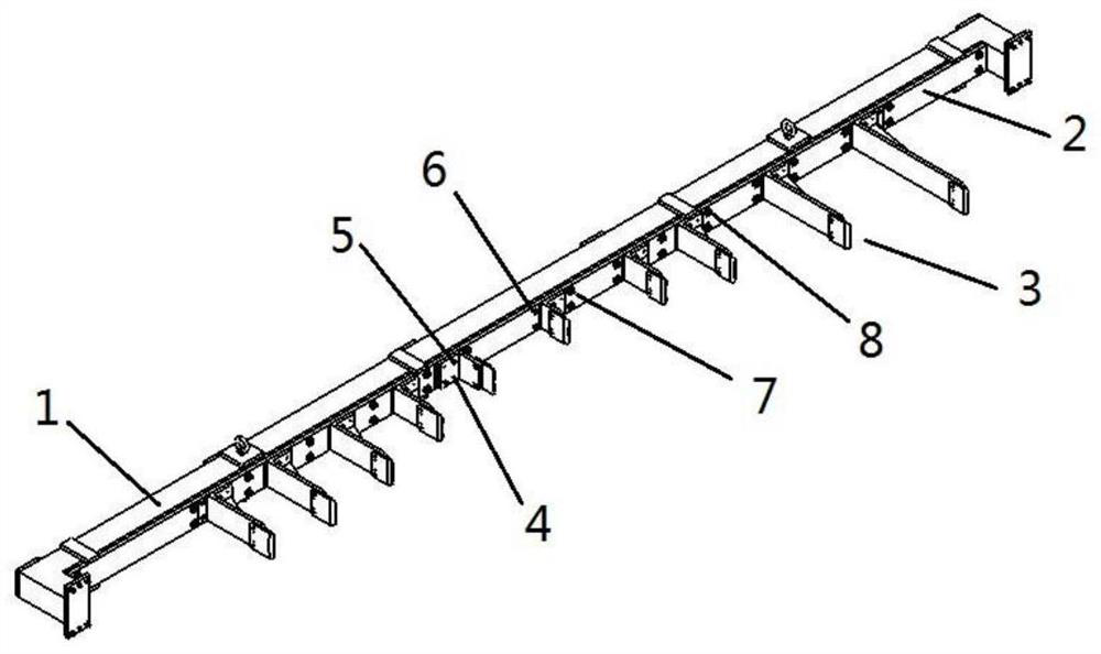
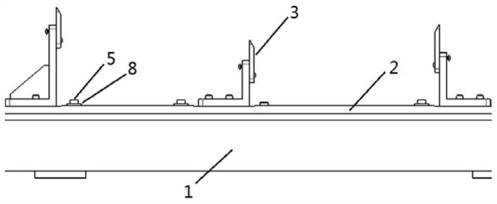
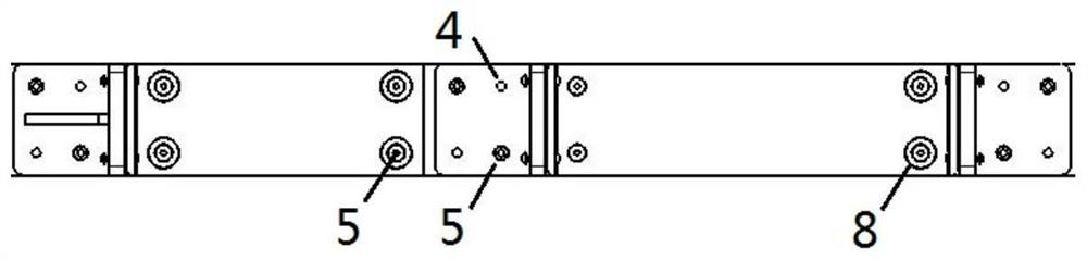
[0017] The present invention will be described in detail below in conjunction with the accompanying drawings. Such as figure 1 As shown, the device includes an upper positioning block 1, a lower positioning block 2 and a mold support 3. The upper positioning block is a C-shaped metal module with chamfers on the inner surface, and the lower positioning block is a T-shaped metal module with chamfers on the outer surface. There is a cooperative relationship between the chamfer of the upper positioning block and the chamfering of the lower positioning block. The inner surface of the upper positioning block matches the outer surface of the lower positioning block. Corresponding to the groove, the lower positioning block is installed in the groove through the positioning block and the round rod 4, so that the lower positioning block rotates around the round rod between 0 and 90 degrees. When the device is applied to the combined mold, the upper positioning block It is fixed on each...


PUM


Abstract

The invention belongs to a composite forming technology, and particularly relates to a long-span beam-type positioning frame, suitable for reinforcements, of a composite reinforced structure. The long-span beam-type positioning frame comprises a positioning clamping plate, a positioning pin, bolts, a steel plate and a positioning frame body; the steel plate and the positioning frame body are combined as a reinforcement positioning frame, the positioning clamping plate is connected to the steel plate, and the steel plate and the positioning frame body are connected in the modes of a circular hole plus a positioning device as well as an oblong hole plus the positioning device through the bolts; the steel plate connected with the positioning clamping plate has the low thermal expansion coefficient, when being heated and then deforming, the positioning frame body can slide relative to the steel plate in the oblong hole, and the positioning clamping plate fixed to the steel plate does not move relatively, so that it is ensured that when deformation of the positioning frame body is large, the position precision of the positioning clamping plate is not influenced; and through the combinational design mode of the steel plate with the low thermal expansion coefficient and the positioning frame body, the positioning precision of the reinforcements during solidification of the composite reinforced structure can be ensured, and the manufacturing cost of the reinforcement positioning frame can also be saved.

Description

technical field [0001] The invention belongs to composite material forming technology, and in particular relates to a long-span beam-type positioning frame suitable for a reinforced structure of composite material. Background technique [0002] Advanced composite materials have unique advantages such as high specific strength, high specific modulus, strong designability, good fatigue fracture resistance, corrosion resistance, good dimensional stability, and easy large-area integral forming. They are increasingly widely used in the aerospace field. After steel, aluminum and titanium, it has rapidly developed into one of the four major aerospace structural materials. The expansion of the application parts and the increase of the amount of advanced composite materials on aerospace vehicles have become one of the symbols to measure the advanced structure and manufacturing level of aerospace vehicles. [0003] Composite reinforced structures generally use a rib positioning frame...

Claims


Application Information

Patent Timeline
Patent Type & Authority Patents(China)
IPC IPC(8): B25B11/00
CPCB25B11/00
Inventor 黄威姚锋毕红艳
Owner AVIC BASIC TECH RES INST
Why Eureka
Try Eureka