A gas-liquid split nozzle for a dyeing machine

A dyeing machine and air jet technology, applied in the field of dyeing, can solve the problems of incomplete penetration of dye liquor, prolonged dyeing time, poor leveling performance, etc. effect of time

Inactive Publication Date: 2016-05-11
高勋绿色智能装备(广州)有限公司
View PDF7 Cites 2 Cited by
  • Summary
  • Abstract
  • Description
  • Claims
  • Application Information

AI Technical Summary

Problems solved by technology

[0004] (1) The air flow needs to atomize the dye liquor in the mixing chamber first, and then blow the fabric through the nozzle to carry out the dyeing at the same time, because the air flow and the dye liquor Inconsistencies in the respective pressures and flow angles before mixing lead to a large amount of turbulent flow when the airflow contacts and atomizes the dye liquor, which wastes a lot of kinetic energy, reduces efficiency, and leads to a sharp increase in energy consumption.
[0005] (2) The air atomization dyeing machine relies on the power of the air flow to pull the fabric forward, requiring high flow and high pressure airflow to pull the fabric, which makes the fan energy consumption high
[0006] (3) The dyeing liquid and the air flow are first atomized and then blown through the nozzle to dye the fabric at the same time. Due to the characteristics of the fabric, the higher the moisture content, the harder it is to fluff and blow off, resulting in the fact that the fabric is often dyed before it is completely fluffy. The process is over, so that the dyeing solution does not penetrate completely, the level dyeing performance is poor, and the color yield is low. To solve this problem, the air atomization dyeing machine can only prolong the dyeing time, increase the amount of auxiliaries and dyes, and blow the cloth to make the cloth fluffy. It is necessary to increase the flow rate and pressure of airflow, dyeing liquor, resulting in an increase in energy consumption and an increase in the total amount of COD emissions;

Method used


Image

  • A gas-liquid split nozzle for a dyeing machine
  • A gas-liquid split nozzle for a dyeing machine

Examples


Embodiment Construction

[0022] The present invention will be further described below in conjunction with specific examples, but the implementation and protection of the present invention are not limited thereto.

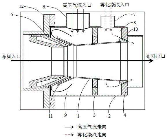
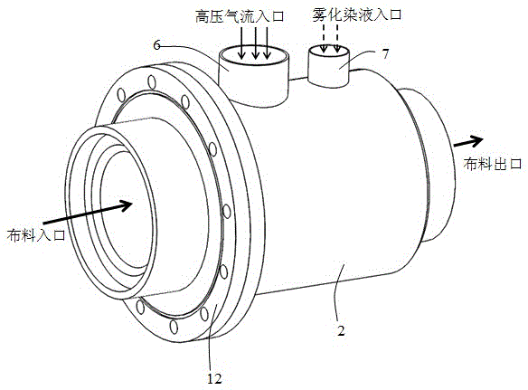
[0023] Such as Figure 1 ~ Figure 2 As shown, a gas-liquid diverting nozzle for a dyeing machine includes a nozzle body 1, a casing 2, a partition 3, an end positioning seat 4, a front positioning sleeve 5, an air inlet pipe 6, and a dye liquor inlet pipe 7; The nozzle body 1 cooperates with the front end positioning sleeve 5 to form a circular frustum-shaped air flow injection channel 11; the nozzle body 1 and the end positioning seat 4 form a circular frustum-shaped dye solution injection flow channel 10; the air flow injection channel 11 and the The injection direction of the dye liquor injection channel 10 forms an included angle of less than 90 degrees with the forward direction of the fabric; the nozzle body 1 is located in the casing 2, and the casing 2, the nozzle body 1, the partit...


PUM


Abstract

The invention discloses a gas-liquid diverting nozzle for a dyeing machine, which includes a nozzle body, a shell, a partition, a terminal positioning seat, a front positioning sleeve, etc., and an air jet flow path, a dye liquor jet flow path, and airflow annular chamber, dye liquor annular chamber; the airflow injection flow path is separated from the dye liquor injection flow path, and the parameters of airflow and dye liquor flow can be independently controlled; the airflow injection flow path is located before the dye liquor injection flow path, and can be first The entangled fabric is fluffy and blown open, and then the dye liquor is sprayed and penetrated, which greatly improves the use efficiency of the dye liquor, improves the leveling performance of the dyeing, the color yield, shortens the dyeing time, and reduces the use of auxiliaries and dyes The total amount can effectively reduce the total amount of COD to achieve the purpose of saving energy, reducing consumption, and being low-carbon and environmentally friendly. The present invention can also prevent uneven dyeing caused by wrinkles of the fabric, fully utilize the impulsive force of the jetting of the dye liquor and the airflow to pull the fabric forward, and reduce the energy consumption of the air-liquid split dyeing machine.

Description

technical field [0001] The invention relates to the technical field of dyeing, in particular to a gas-liquid split nozzle for a high-temperature, high-pressure gas-liquid split dyeing machine. Background technique [0002] Currently widely used dyeing machines mainly include two types according to the dyeing principle: overflow dyeing machine and air atomization dyeing machine. The overflow dyeing machine has the disadvantages of large liquor ratio, high power consumption, many dyeing and chemical auxiliaries, and long process time, and the dyeing quality also has problems such as creases on the fixed cloth surface and poor tubes. The air atomization dyeing machine adopts the principle of aerodynamics, and uses the air nozzle to atomize and spray the dye solution onto the fabric, so as to solve the various shortcomings of the overflow dyeing machine, and gradually become the mainstream dyeing technology. The nozzle is the core key part of the air atomization dyeing machine....

Claims


Application Information

Patent Timeline
Patent Type & Authority Patents(China)
IPC IPC(8): D06B1/02B05B7/08
Inventor 萧振林陈晓辉
Owner 高勋绿色智能装备(广州)有限公司
Why Eureka
Try Eureka