Cast-in-site rigid bone self-heat-preservation wall body, building blocks and wall building method
A technology of self-insulating blocks and cast-in-place rigid bones, which is applied to walls, building materials, and building components, and can solve problems such as cumbersome processes, low production capacity, and low compressive strength
- Summary
- Abstract
- Description
- Claims
- Application Information
AI Technical Summary
Problems solved by technology
Method used
Image
Examples
specific Embodiment approach 1
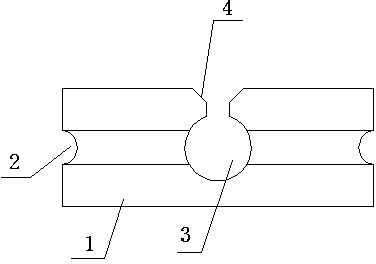
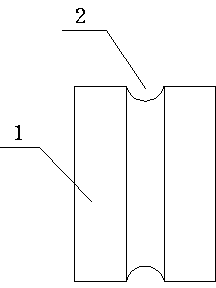
[0035] by attaching figure 1 , 2 , 7 It can be seen that a block for cast-in-place rigid-frame self-insulating walls of this scheme includes a concrete self-insulating block body 1, and grooves are arranged on the upper and lower parts of the concrete self-insulating block body 1 2. Both ends of the concrete self-insulating block body 1 are provided with grooves 2, and a through hole 3 penetrating through the concrete self-insulating block body 1 is provided in the middle of the concrete self-insulating block body 1, and the side wall of the through hole has Opening 4. The opening 4 is V-shaped, and the distance between the side of the opening 4 away from the through hole 3 is greater than the distance between the side of the opening 4 and the side close to the through hole 3 .
[0036] The thermal conductivity of the concrete self-insulating block body 1 is less than 0.041. The concrete self-insulating block body 1 is a polyphenylene granular concrete self-insulating block...
specific Embodiment approach 2
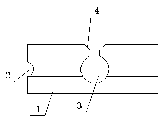
[0042] by attaching image 3 , 4 , 7 It can be seen that the difference between this embodiment and Embodiment 1 is that the upper and lower parts of the concrete self-insulating block body 1 are provided with grooves 2, and one end of the concrete self-insulating block body 1 is provided with grooves 2 .
[0043] The method for building a cast-in-place rigid frame self-insulation wall by using the above-mentioned concrete self-insulation blocks is characterized in that it comprises the following steps:
[0044] a. Pre-set criss-cross rigid frame support, which is a support composed of steel bars and wire ropes at the same time, and the vertical rigid frame interval distance is the same as the length of the concrete self-insulating block;
[0045] b. Lay prefabricated concrete self-insulation blocks 1 on the rigid frame support, one end of all concrete self-insulation blocks 1 with the groove 2 faces the same side, and the vertical rigid frame enters the through hole through...
specific Embodiment approach 3
[0047] by attaching Figure 5 , 6 , 7 It can be seen that the difference between this embodiment and Embodiment 1 is that the upper or lower part of the concrete self-insulating block body 1 is provided with a groove 2, and both ends of the concrete self-insulating block body 1 are provided with grooves 2.
[0048]The method for building a cast-in-place rigid frame self-insulation wall by using the above-mentioned concrete self-insulation blocks is characterized in that it comprises the following steps:
[0049] a, preset criss-cross rigid frame supports, the rigid frame supports are bamboo pole supports, and the vertical rigid frame spacing distance is the same as the length of the concrete self-insulation block;
[0050] b. Prefabricated concrete self-insulation blocks 1 are laid on the rigid frame support, and all the concrete self-insulation blocks 1 have grooves 2 on the upper or lower part at the same time downward or upward, and the vertical rigid frame passes through...
PUM
 Abstract
Description
Claims
Application Information
 - R&D
- Intellectual Property
- Life Sciences
- Materials
- Tech Scout
- Unparalleled Data Quality
- Higher Quality Content
- 60% Fewer Hallucinations
Browse by: Latest US Patents, China's latest patents, Technical Efficacy Thesaurus, Application Domain, Technology Topic, Popular Technical Reports.
© 2025 PatSnap. All rights reserved.Legal|Privacy policy|Modern Slavery Act Transparency Statement|Sitemap|About US| Contact US: help@patsnap.com


