Electric daylighting and smoke exhaust louver

A skylight, electric technology, applied in the direction of roof, building, building structure, etc., can solve the problems of safety hidden danger of building fire and smoke exhaust application, small effective ventilation area, opening time restriction, etc., to achieve strong ability to adapt to natural climate changes, reduce Energy consumption to adjust the cooling time and improve the effect of energy saving

Active Publication Date: 2014-09-17
锦州鹏翔电力轻钢设备有限公司
View PDF6 Cites 5 Cited by
  • Summary
  • Abstract
  • Description
  • Claims
  • Application Information

AI Technical Summary

Problems solved by technology

[0005] In terms of fire and smoke exhaust functions, the existing lighting and smoke exhaust skylights are not conducive to the emergency function requirements of fire and smoke exhaust: 1. The lighting and smoke exhaust skylights are closed for a long time, which cannot meet the daily building energy-saving ventilation and fire emergency smoke exhaust requirements
2. The daylighting and smoke exhaust skylight does not shelter from the wind, and the ventilation and smoke exhaust are greatly affected by the external wind force; the effective ventilation area of ​​the product is small, and the ventilation performance is low, technically unable to guarantee the massive and rapid smoke exhaust function required by fire protection
3. The daylighting and smoke exhaust skylight adopts a power window opening mechanism to overcome the gravity of the window sash by side rotation or horizontal translation, and the opening time is limited by the mechan

Method used


Image

  • Electric daylighting and smoke exhaust louver
  • Electric daylighting and smoke exhaust louver

Examples


Embodiment Construction

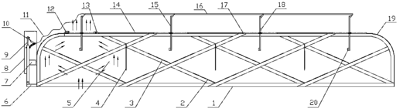
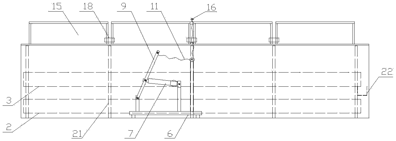
[0026] As shown in the figure, the electric daylighting and smoke-exhausting skylight includes a truss structure 1 arranged on the basis of building roof vents and connected with each other by multiple rows of truss purlins 21 arranged side by side. As a preference, this embodiment uses five rows of truss purlins 21 as an example, five rows of truss purlins 21 are connected to each other through a plurality of evenly distributed longitudinal rods 17 . Windshields 19 are fixed around the truss structure 1, and upper, middle and lower layers of rainshields are evenly arranged on the truss structure 1 respectively. The upper rain shield 14 is a flat plate, the middle rain shield 3 and the lower rain shield 2 are V-shaped, the lower rain shield 2 is located directly below the corresponding upper rain shield 14, and the middle rain shield 3 is located at the opposite side. Between the two groups of adjacent upper and lower rain shields, the middle rain shield 3 has a certain degree...


PUM


Abstract

The invention discloses an electric daylighting and smoke exhaust louver, which comprises a truss structure, a wind shield and a flashing are arranged around the truss structure, an upper layer of rain shields, a middle layer of rain shields and a lower layer of rain shields are evenly arranged on the truss structure, splash-proof nets which are located between the upper layer of rain shields and the lower layer of rain shields are arranged on the truss structure, and wind-shielding valve plates which are connected with one another through connecting rods are articulated with the truss structure; an electric driver which is connected with the wind-shielding valve plates is also arranged on the truss structure, and the wind-shielding valve plates can be automatically opened in a vertical state after the power of the electric driver is off. The electric daylighting and smoke exhaust louver has the advantages that: the electric daylighting and smoke exhaust louver has both a daylighting and ventilation function and a fire-fighting smoke exhaust function for buildings, and can meet the requirements of buildings on daily energy-saving ventilation regulation and fire-fighting emergency massive ventilation; by means of the wind-shielding valve plates, power-off automatic opening can be realized, the ventilation and smoke exhaust passage can be quickly opened within one second, consequently, the function of quick opening for smoke exhaust required by fire fighting can be ensured, and more time can be bought for the escape of people when a fire breaks out in a building.

Description

technical field [0001] The invention relates to a public building environment energy-saving technology and a building fire safety facility technology, in particular to an electric daylighting and smoke-exhausting skylight. Background technique [0002] For a long time, the natural lighting and ventilation design of public buildings has basically adopted the national standard "Electric Skylight for Lighting and Smoke Exhaust" (09J621-2). According to the current building energy-saving design "ventilation and fire-fighting and smoke-exhaust shared" functional requirements, daylighting and smoke-exhausting skylights, on the one hand, as building energy-saving environmental technology, have the daily lighting and ventilation functions of buildings; It can be opened quickly to ensure the fire and smoke exhaust function of the building, and can be closed immediately according to fire protection needs. But the existing daylighting and smoke exhaust skylight technology does not hav...

Claims


Application Information

Patent Timeline
IPC IPC(8): E04D13/035
Inventor 单连勤李佰库单晓晴韦福利曹凯鲁宇新
Owner 锦州鹏翔电力轻钢设备有限公司
Why Eureka
Try Eureka