Down-hole liquid release device and method for oil and gas fields

A release device, oil and gas field technology, applied in earth-moving drilling, wellbore/well components, cleaning appliances, etc., can solve the problems of difficult to control the release speed, difficult to ensure uniform release of drugs, etc., to achieve the effect of continuous release

Active Publication Date: 2014-09-17
PETROCHINA CO LTD
View PDF5 Cites 4 Cited by
  • Summary
  • Abstract
  • Description
  • Claims
  • Application Information

AI Technical Summary

Problems solved by technology

The dosing rate depends on the release rate of the solid agent, and the release rate of the agent is greatly affected by the properties of the curing agent itself, the curing process, the downhole temperature, the flow rate, the contact area between the agent and the well fluid, etc. Due to the complex downhole conditions, the release rate is difficult. Control, therefore, it is difficult to ensure uniform drug release

Method used


Image

  • Down-hole liquid release device and method for oil and gas fields
  • Down-hole liquid release device and method for oil and gas fields

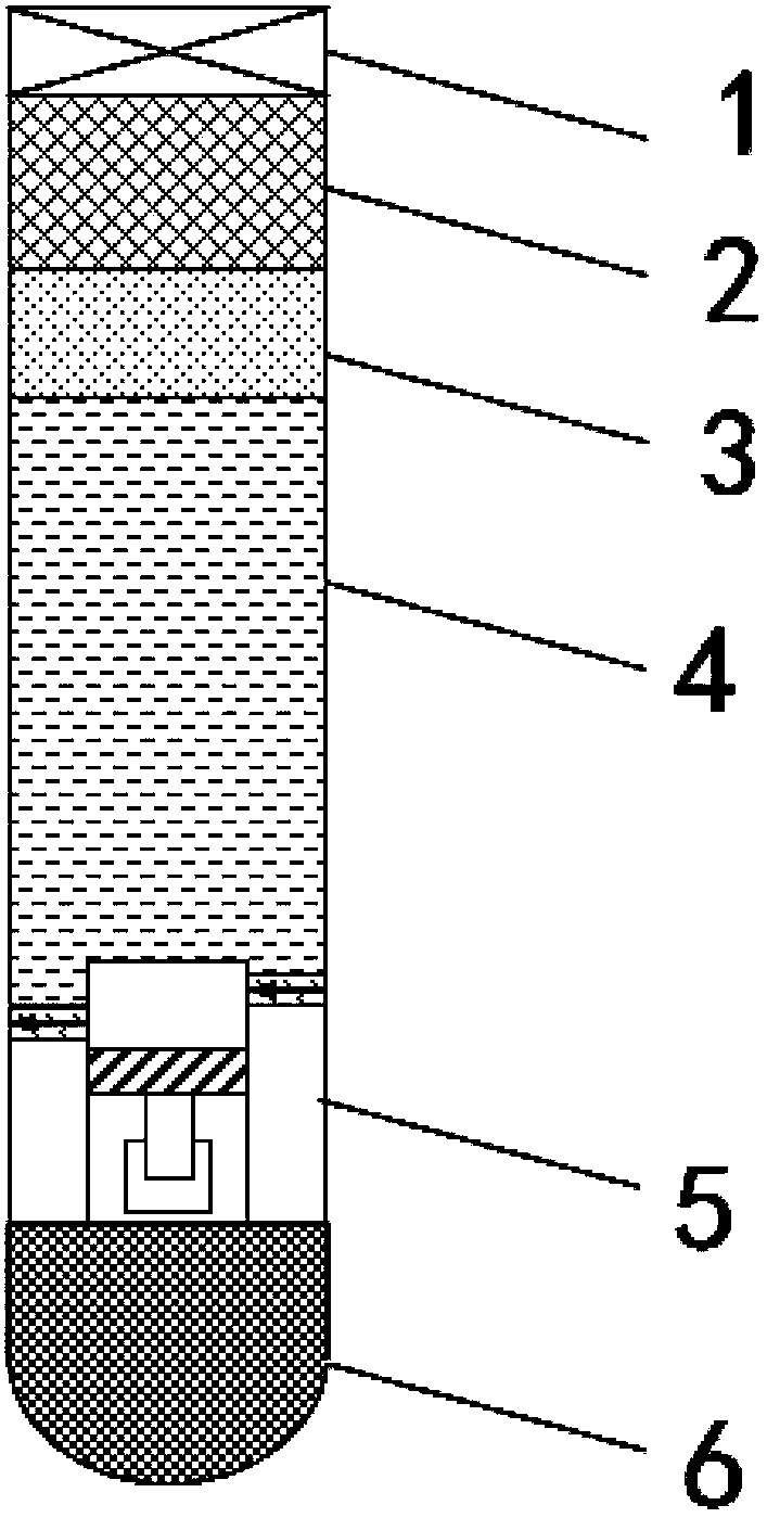
Examples


Embodiment 1

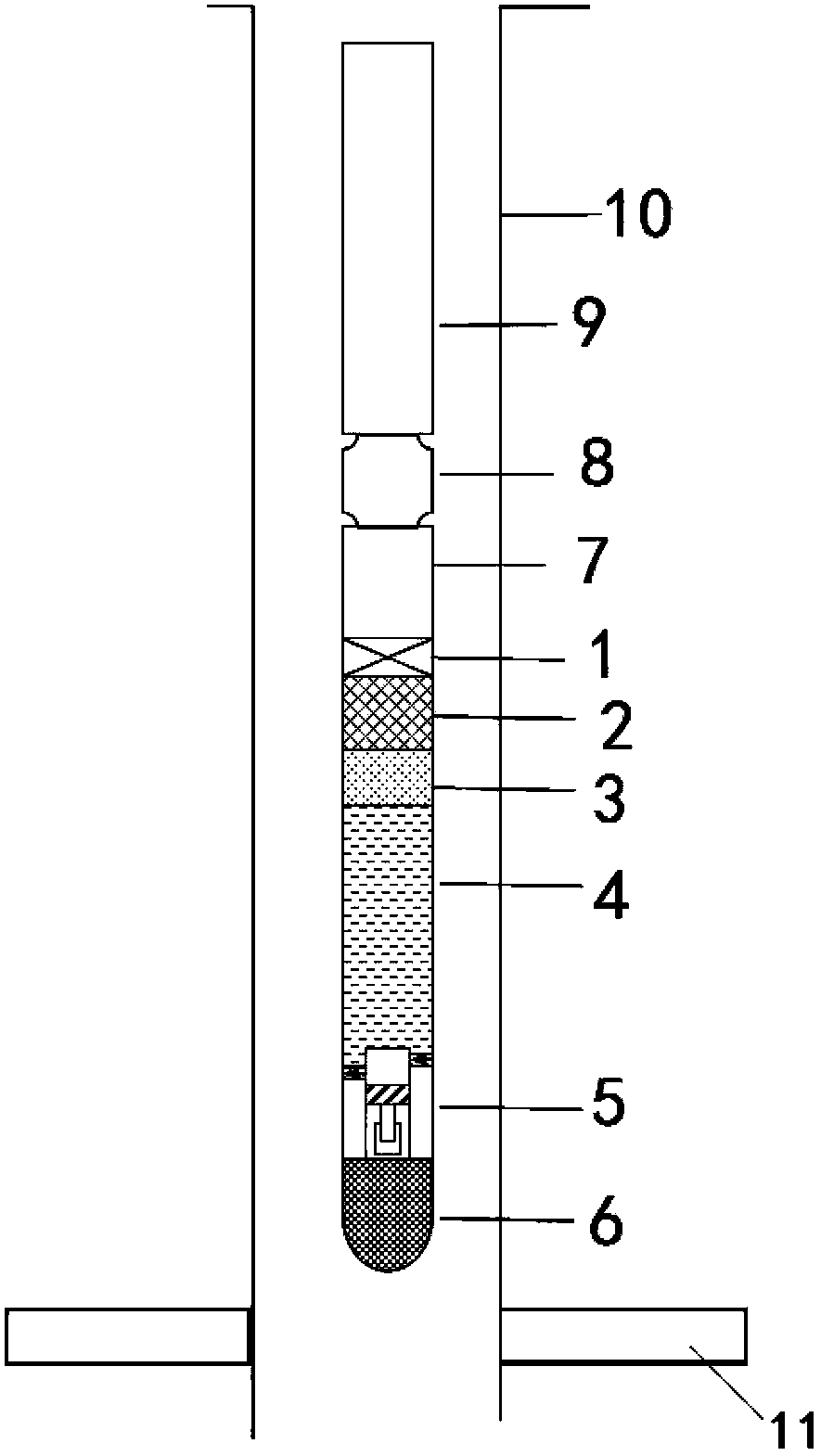
[0019] Embodiment 1: as figure 1 , figure 2 as shown,

[0020] In the figure, 01 plug, 02 liquid inlet pipe, 03 separation liquid, 04 liquid storage pipe, 05 piston pump, 06 battery nipple

[0021] 01 Plug, 02 Inlet pipe, 03 Partition liquid, 04 Storage pipe, 05 Piston pump, 06 Battery nipple

[0022] A downhole liquid release device for oil and gas fields, consisting of a plug 1, a liquid inlet pipe 2, a separation liquid 3, a liquid storage pipe 4, a piston pump 5, and a battery nipple 6; the battery nipple 6 is connected to the piston through a collar and a thread The pump 5 and the piston pump 5 are connected to the liquid storage pipe 4 through a coupling and a threaded thread, the liquid storage pipe 4 is connected to the liquid inlet pipe 2 through a coupling and a threaded thread, the liquid inlet pipe 2 is connected to the plug 1 through a coupling and a threaded thread, and the storage There is a separation liquid 3 or a separation liquid layer between the liquid...

Embodiment 2

[0025] Taking an oil well as an example, the well casing is API standard 5 1 / 2 Well Production Tubing is API Standard 2 7 / 8 Oil pipe, the average pump inspection cycle is 1 year, the daily liquid production volume is 50 cubic meters, and the liquid production density is 0.92g / cm 3 , in order to ensure the normal production of the oil well, it is necessary to continuously add 20ppm of oil with a density of 1.2g / cm2 to the well every day 3 Drug A.

[0026] Calculate and set the release speed of the piston pump to 0.58ml / min based on the above data. When the oil well is completed, connect the battery nipple to the piston pump and 11 2 7 / 8 Liquid storage tube, add 365 kg (about 304 liters) of drug A to the liquid storage tube, and then add 3 kg 3 separator fluid. Connect the inlet tube and plug. Finally, the device is connected to the lowermost end of the production tubing through a coupling. Since the plug is at the uppermost end, the device is not directly connected to the ...


PUM


Abstract

The invention discloses a down-hole liquid release device and a down-hole liquid release method for oil and gas fields and belongs to the technical field of oil and gas field development. The down-hole liquid release device filled with agents is connected to the lower part of a production pipe column and descends to the bottom of an oil well, a piston pump starts to work according to set parameters, and the agents are released into the oil well from a liquid storage pipe at a certain flowing speed and act on the oil well. Along with the release of the liquid agents, the quantity of the agents in the liquid storage pipe is decreased, the liquid level descends, a separating liquid piston moves downwards, and liquid in a shaft enters the liquid storage pipe through a liquid inlet pipe, so that the pressure balance of a system is ensured; the liquid entering the shaft cannot be mixed with the liquid agents in the liquid storage pipe due to the separating liquid piston.

Description

technical field [0001] The invention relates to a downhole liquid release device and method for oil and gas fields, belonging to the technical field of oil and gas field development. Background technique [0002] In the process of oil field development, it is often necessary to add various chemical agents to oil wells to achieve the purposes of anti-corrosion, anti-scaling, anti-wax, etc., reduce production failures of oil wells, and maintain normal production of oil wells. [0003] At present, there are mainly two methods of dosing in oil wells: liquid wellhead dosing and solid downhole slow-release dosing. Liquid wellhead dosing is to add the medicine from the wellhead to the annulus of the oil casing, and the medicine flows downhole under the action of gravity. Due to the small amount of chemical agent added, plus its own volatilization and pipe wall adsorption, the amount of chemical agent reaching the wellbore cannot meet the design requirements. In addition, manual m...

Claims


Application Information

Patent Timeline
Patent Type & Authority Applications(China)
IPC IPC(8): E21B37/06
Inventor 尹玉川孙忠杰邓生辉熊汉辉陈超徐浩王勇呼惠娜贺永殿雷斌王柳
Owner PETROCHINA CO LTD
Why Eureka
Try Eureka