
Arrangement to measure the deflection of a blade of a wind turbine

A technology of wind turbines and blades, which is applied in the field of deflection devices, can solve problems such as time-consuming and delicate, the system is not suitable for a long period of time, and is expensive, and achieve the goals of reducing complexity, increasing life, high accuracy and sampling rate Effect

Inactive Publication Date: 2014-09-17
SIEMENS AG
View PDF3 Cites 6 Cited by
  • Summary
  • Abstract
  • Description
  • Claims
  • Application Information

AI Technical Summary

Problems solved by technology

The installation of the gauges and the corresponding bus system for the transmission of the measurement data is rather expensive and time-consuming and delicate
The entire system is not suitable for long periods of time since the entire equipment of the system may be exposed to lightning strikes

Method used


Image

  • Arrangement to measure the deflection of a blade of a wind turbine

Examples


Embodiment Construction

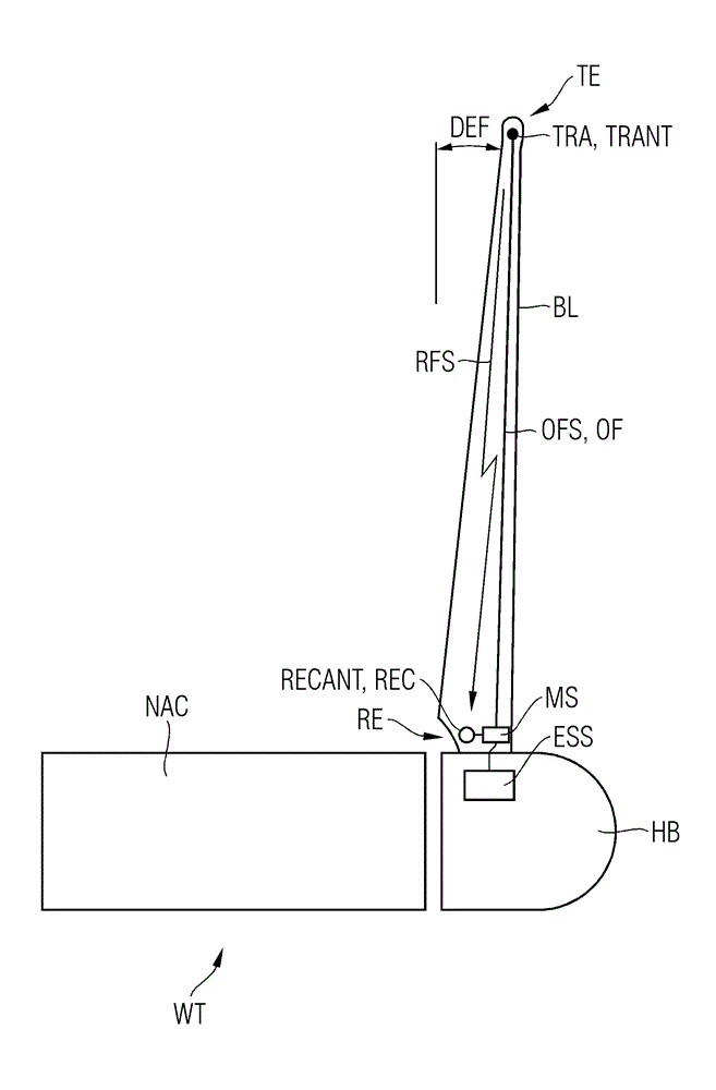
[0062] The wind turbine WT shown in "cutaway" in this figure shows the nacelle NAC, the hub HB and the blades BL.

[0063] A transmitter TRA with integrated antenna TRANT is arranged close to the tip of the blade.

[0064] The transmitter TRA is preferably arranged into a blade cavity extending from the root end RE of the blade BL to the tip end TE of the blade BL.

[0065] A receiver REC with integrated antenna RECANT is arranged at the root end RE of the blade BL.

[0066] The receiver REC is preferably arranged into a blade cavity extending from the root end RE of the blade BL to the tip end TE of the blade BL.

[0067] The transmitter TRA and the receiver REC prepare radio frequency based signaling for monitoring signals. The monitoring signal transmitted from the transmitter TRA to the receiver REC via the RF connection is denoted monitoring signal RFS.

[0068] The monitoring system MS is arranged close to the receiver REC and into the blade cavity.

[0069] The surv...


PUM


Abstract

According to the arrangement invented the deflection of a blade of a wind turbine is determined. A transmitter is arranged close to the tip end of the blade, while a receiver is arranged close to the root end of the blade. The transmitter and the receiver are prepared for a wireless transfer of a monitoring signal, which is sent from the transmitter to the receiver. A monitoring system is arranged close to the root end of the blade. The monitoring system is prepared to generate the monitoring signal. The monitoring system is connected with the transmitter by a cable-bound communication line, thus the monitoring signal is transferred from the monitoring system to the transmitter. The monitoring system is even connected with the receiver, thus the monitoring signal is transferred from the receiver to the monitoring system. The monitoring system is prepared to determine the deflection of the blade based on the transferred monitoring signal.

Description

technical field [0001] The invention relates to a device for measuring the deflection of a blade of a wind turbine. Background technique [0002] The blades of modern wind turbines exhibit lengths of 45 meters or more. The blade is optimized for its weight, for its aerodynamic properties and for the best possible generation of electrical power based on the properties of the blade. [0003] Therefore, sooner or later this optimization will lead to rather flexible and long blades. Due to the flexibility of the blades, the problem arises that the tips of the rotating blades of a wind turbine in operation may hit the tower. [0004] The distance between the tower and the blade tip is also referred to as "blade tip / tower clearance". [0005] It is known to measure the deflection of a rotating blade by monitoring the tip of the blade. [0006] One possibility is to attach strain gauges on the blade surface. It is mainly used for testing purposes to gather some knowledge about...

Claims


Application Information

Patent Timeline
Patent Type & Authority Applications(China)
IPC IPC(8): F03D7/02G01S3/78G01S17/42
CPCG01B15/06F03D11/0091F03D7/06F03D7/00G01S13/08F03D17/00F05B2270/17Y02E10/74Y02E10/72
Inventor P.埃格达尔J.W.斯塔埃达尔A.齐罗夫
Owner SIEMENS AG
Learn More