Improved adsorption type heat pump and adsorption-desorption method of improved adsorption type heat pump

An adsorption heat pump and an improved technology, applied in the field of adsorption heat pump, can solve the problems of small refrigeration performance coefficient, low refrigeration power, low effective adsorption capacity of adsorbent, etc., and achieve the effect of light weight and low power consumption

Inactive Publication Date: 2014-09-17
GUANGZHOU INST OF ENERGY CONVERSION - CHINESE ACAD OF SCI
View PDF6 Cites 0 Cited by
  • Summary
  • Abstract
  • Description
  • Claims
  • Application Information

AI Technical Summary

Problems solved by technology

However, ordinary adsorption heat pumps only rely on the pressure difference between the adsorption bed and the evaporator/condenser to push the refrigerant to move in the whole system, and the effective adsorption amount of th

Method used


Image

  • Improved adsorption type heat pump and adsorption-desorption method of improved adsorption type heat pump
  • Improved adsorption type heat pump and adsorption-desorption method of improved adsorption type heat pump
  • Improved adsorption type heat pump and adsorption-desorption method of improved adsorption type heat pump

Examples


Embodiment 1

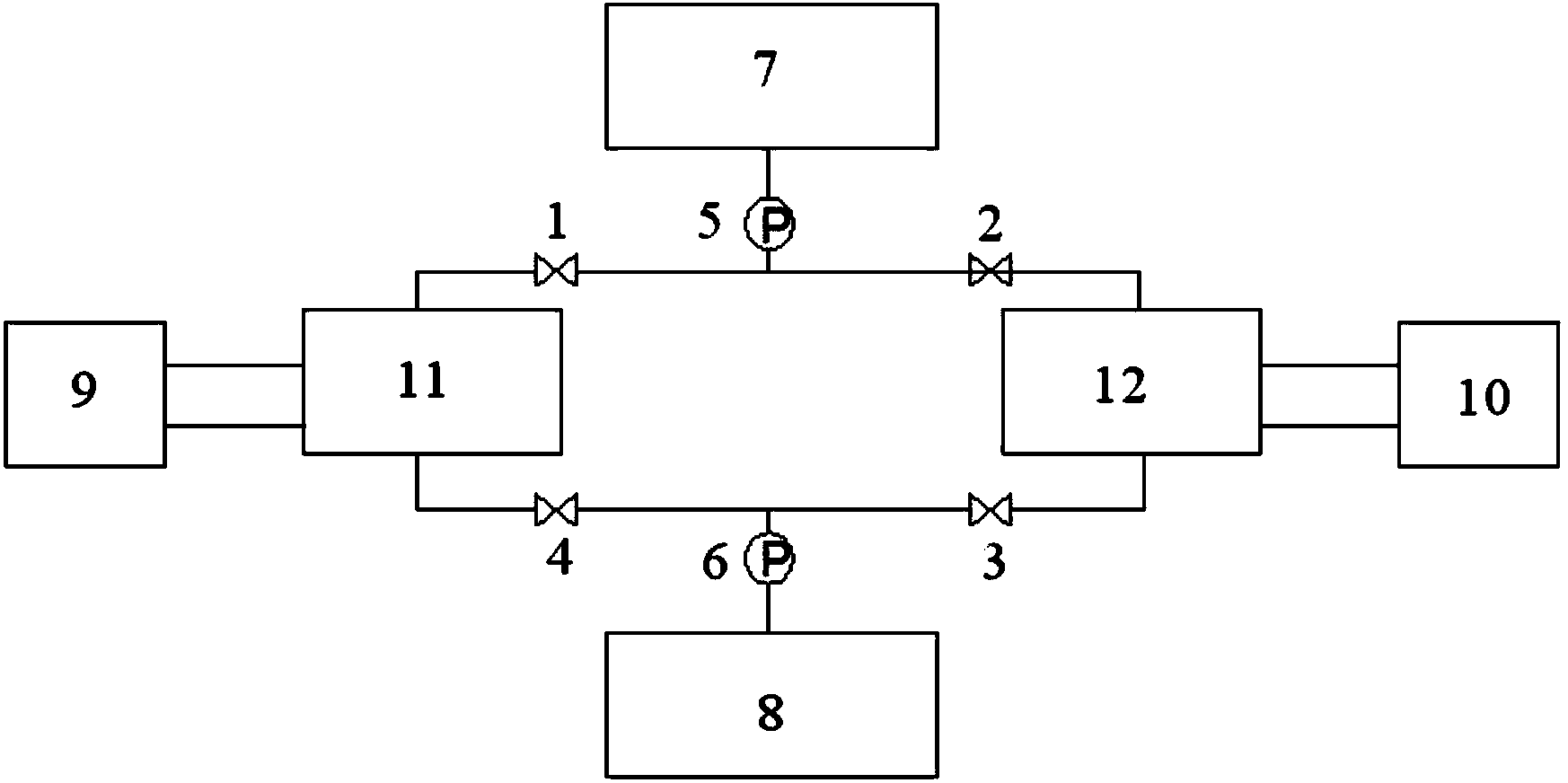
[0027] like Figure 1a As shown, an improved adsorption heat pump includes a first adsorption bed 11, a second adsorption bed 12, a condenser 7, an evaporator 8, a first vacuum booster pump 5, a second vacuum booster pump 6 and related valves wherein one end of the first adsorption bed 11 is connected to the condenser 7 through the first valve 1, the first vacuum booster pump 5 to form a loop; the other end of the first adsorption bed 11 is through the fourth valve 4, the second The vacuum booster pump 6 is connected to the evaporator 8 through a pipeline to form a loop; one end of the second adsorption bed 12 is connected to the second valve 2 through a pipeline, and is connected to the first valve 1 and the first vacuum booster pump 5. The pipeline is connected to the condenser 7 through the first vacuum booster pump 5 to form a loop; the other end of the second adsorption bed 12 is connected to the third valve 3 through the pipeline, and is connected to the fourth valve 4 an...

Embodiment 2

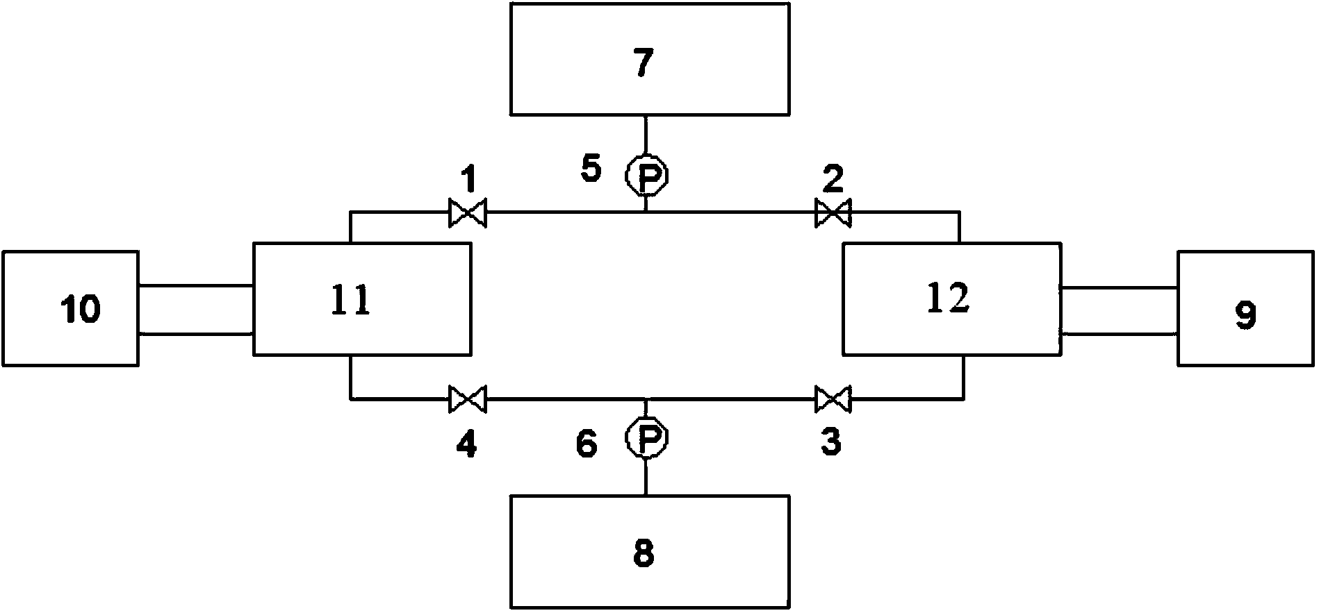
[0032] like Figure 1b As shown, an improved adsorption heat pump, the first adsorption bed 11 and the second adsorption bed 12 are respectively connected with the heat source system 10 and the cooling water system 9 to form corresponding waterways. The working process of an adsorption heat pump with a vacuum booster pump (taking refrigeration as an example): when the second adsorption bed 12 performs adsorption, the first adsorption bed 12 is connected to the cooling water system 9, and the gaseous refrigerant evaporates from the evaporator 8 After being pressurized by the second vacuum booster pump 6, it enters the adsorbent layer through the third valve 3 to complete the adsorption process; when the first adsorption bed 11 is desorbed, the first adsorption bed 11 and the heat source system 10 Then, the gaseous refrigerant is desorbed from the first adsorption bed 11, passes through the first valve 1, the first vacuum booster pump 5, and after being pressurized, enters the c...


PUM


Abstract

The invention discloses an improved adsorption type heat pump. The improved adsorption type heat pump comprises a first adsorption bed, a second adsorption bed, a condenser, an evaporator, a first vacuum booster pump and a second vacuum booster pump, wherein one end of the first adsorption bed passes through a first valve and the first vacuum booster pump and is connected with the condenser through a pipeline; the other end of the first adsorption bed passes through a fourth valve and the second vacuum booster pump and is connected with the evaporator through a pipeline; one end of the second adsorption bed is connected with a second valve through a pipeline, is connected to a pipeline between the first valve and the first vacuum booster pump and is connected with the condenser through the first vacuum booster pump; the other end of the second adsorption bed is connected with a third valve through a pipeline, is connected to a pipeline between the fourth valve and the second vacuum booster pump and is connected with the evaporator through the second vacuum booster pump. According to the improved adsorption type heat pump, the effective adsorption amount of an adsorbent adsorption/desorption process can be improved and the refrigeration effect of the adsorption type heat pump is improved.

Description

technical field [0001] The invention relates to a novel adsorption heat pump with a vacuum booster pump and an adsorption-desorption method using the adsorption heat pump, belonging to the technical field of adsorption refrigeration. Background technique [0002] At present, the utilization rate of industrial waste heat in my country is relatively low, especially for low-grade industrial waste heat. Due to the low heat energy density and low recovery efficiency, it is basically discharged directly, and energy waste is serious. As a clean and cheap renewable energy, how to realize efficient utilization, It is of great significance in alleviating energy shortage. Adsorption heat pumps can use low-grade thermal energy such as industrial waste heat above 60°C and solar energy to generate cold energy, and replace ordinary electric compression air conditioners with heat for refrigeration, saving the power consumption of air-conditioning and cooling. An important measure for effici...

Claims


Application Information

Patent Timeline
IPC IPC(8): F25B17/00
CPCY02B30/64Y02B30/62Y02A30/27Y02B30/00
Inventor 黄宏宇小林敬幸何兆红袁浩然邓立生呼和涛力窪田光宏陈勇
Owner GUANGZHOU INST OF ENERGY CONVERSION - CHINESE ACAD OF SCI
Why Eureka
Try Eureka