
A method for detecting fixed tire frame markings based on step-by-step conversion of spatial coordinate data

A technology of spatial coordinates and detection methods, applied in the field of surveying and mapping, can solve the problems of difficult prediction and preprocessing, increase the difficulty of marking and testing the tire frame, and difficult to organize the precision control data, etc., and achieve the effect of ensuring the marking precision.

Inactive Publication Date: 2016-04-20
JIANGSU MARITIME INST
View PDF8 Cites 0 Cited by
  • Summary
  • Abstract
  • Description
  • Claims
  • Application Information

AI Technical Summary

Problems solved by technology

This kind of operation method is often difficult to describe the fixed tire frame in the area as a whole, and it is difficult to realize the prediction and pretreatment of its state, which increases the difficulty of tire frame marking and detection
Moreover, this two-dimensional detection method requires more operators on site. Taking the middle group segmented tire frame as an example, 3 people are needed to determine the direction of the theodolite, 3 people are required to determine the level of the level, and 3 people are required to measure the distance with a steel tape. 4 hours, which greatly reduces tire frame marking / detection efficiency and accuracy, and directly affects the quality of segmented construction
The traditional marking data of the fixed tire frame is distance and height, which is difficult to organize into effective precision control data, which is not conducive to precision evaluation and archiving, and the operation precision and efficiency are directly related to the proficiency of the operating personnel and the tacit understanding of the cooperating personnel. Accuracy has a large human interference factor

Method used


Image

  • A method for detecting fixed tire frame markings based on step-by-step conversion of spatial coordinate data
  • A method for detecting fixed tire frame markings based on step-by-step conversion of spatial coordinate data
  • A method for detecting fixed tire frame markings based on step-by-step conversion of spatial coordinate data

Examples


Embodiment Construction

[0033] The present invention will be described in further detail below in conjunction with the accompanying drawings.

[0034] A method for detecting fixed tire frame markings based on the step-by-step conversion of spatial coordinate data includes the following steps:

[0035] 1. Step-by-step conversion of spatial coordinate data:

[0036] According to the measurement method of plane coordinates and elevation coordinates, the two are converted step by step to establish a high-precision three-dimensional coordinate transformation model;

[0037] 1. Transformation of plane coordinates:

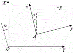
[0038] Such as figure 2 , let the coordinate system O—XY be the measurement coordinate system, the coordinate system A-xy be the station coordinate system, and p be any point in the station coordinate system A-xy; the relationship between the two coordinate systems is as follows:

[0039] x p ...


PUM


Abstract

The invention discloses a fixed molding bed scribing monitoring method based on a total station. The method provides two coordinate orientation mode and two scribing patterns. The method comprises the following steps: according to design requirements of a fixed molding bed, establishing a spatial three-dimensional coordinate system of a fixed molding bed area along original points, an X-axis direction or a Y-axis direction; automatically calculating the horizontal angle and the vertical angle of a position where a to-be-scribed point is located in virtue of space coordinate matching techniques and directing the total station to carry out automatic scribing, or directing operating personnel to carry out manual scribing; carrying out automatic correction on deviation occurred in measurement of the to-be-scribed point until systematic deviation setting requirements are met; and carrying out three-dimensional coordinate measuring and checking on the scribed fixed molding bed. The invention has the following beneficial effects: compared with traditional fixed molding bed scribing methods based on a steel tape, a theodolite and a range finder, the method provided by the invention only needs two persons for operation on the spot and has the characteristics of high scribing precision, a high degree of automation, high work efficiency, high security, etc.

Description

technical field [0001] The invention relates to a marking method for a fixed tire frame, which belongs to the technical field of surveying and mapping. Background technique [0002] The fixed tire frame is a special process equipment used to support the construction of the hull section and ensure the accuracy of its shape according to the line shape of the relevant parts of the hull section. When building a ship section, the main purpose of the tire frame is to support the weight of the section and ensure the line shape of the section. In the existing shipbuilding field, the precision of shipbuilding is generally required to reach the millimeter level or even submillimeter level, which puts forward a higher standard for the marking / inspection of the fixed tire frame. Fixed tire frame marking refers to marking the designed position and height of each tire frame support point to the actual point within the range of tolerance requirements. In the construction of high-precisio...

Claims


Application Information

Patent Timeline
Patent Type & Authority Patents(China)
IPC IPC(8): G01C15/00
CPCB25H7/00G01C15/00
Inventor 方露魏叶青谢荣
Owner JIANGSU MARITIME INST
Learn More