Optical cable of improved structure

An optical cable and optical fiber technology, applied in the direction of fiber mechanical structure, etc., can solve the problems of high investment, complex equipment, uneconomical, etc., and achieve the effects of easy construction, material consumption and space saving.

Inactive Publication Date: 2014-09-17
尹红
View PDF4 Cites 4 Cited by
  • Summary
  • Abstract
  • Description
  • Claims
  • Application Information

AI Technical Summary

Problems solved by technology

Among them, all the optical fiber ribbons or optical fibers are placed in the skeleton groove, and it can be taken out from a single skeleton groove during construction, so it is very popular with users. However, according to the skeleton type optical cable in the industry standard, complex equipment is required to process the skeleton groove , high investment, very uneconomical

Method used


Image

  • Optical cable of improved structure
  • Optical cable of improved structure
  • Optical cable of improved structure

Examples


Embodiment 1

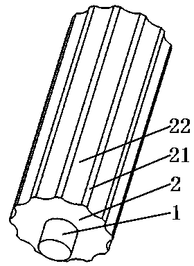
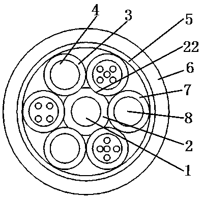
[0036] please see Figure 1 to Figure 4 , an optical cable with an improved structure, which includes 12 loose tubes 4, a protective layer 5 outside the loose tubes, a sheath layer 6 that is extruded and coated outside the protective layer, and in each loose tube It has 4 optical fibers 3; it is characterized in that it also includes a support member located in the center of the optical cable, the support member is composed of a central strengthening member 1, a support member 2 coated outside the strengthening member, and the outer edge of the support member is composed of The protruding ribs 21 and the concave grooves 22 are distributed at intervals between the ribs and the grooves; only a part of each loose tube is located in the groove, and adjacent loose tubes are tangent.

Embodiment 2

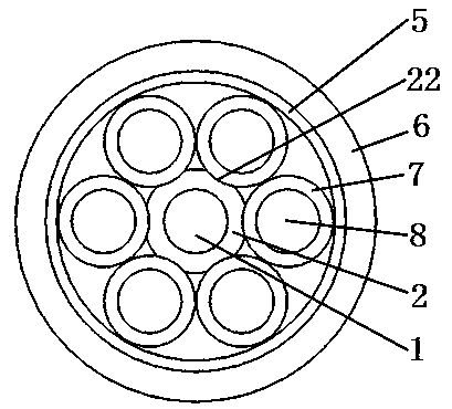
[0038] please see Figure 5 and Figure 8 , an optical cable with an improved structure, which includes more than 6 loose tubes 4, a protective layer 5 outside the loose tube, a sheath layer 6 that is extruded and coated outside the protective layer, and each loose tube It has at least 4 optical fibers 3; it is characterized in that it also includes a support member located in the center of the optical cable, the support member is composed of a central strengthening member 1, a support member 2 coated outside the strengthening member, and the outer edge of the support member There are protruding ribs 21 and concave grooves 22, and the ribs and the grooves are distributed at intervals; only a part of each loose tube is located in the groove, and adjacent loose tubes are tangent.

[0039]Of course, the optical cable with an improved structure described in the above-mentioned implementation example 1 and implementation example 2 is characterized in that the loose tubes can be ot...

Embodiment 3

[0042] please see Figure 9 , and refer to Figure 5 to Figure 8 , an optical cable with an improved structure, which includes 3 loose tubes 4, 3 insulated core wires 7, a protective layer 5 outside the loose tube and the insulated core wires, and a protective layer coated by extrusion The sheath layer 6 has at least 4 optical fibers 3 in each loose tube, and each insulated core wire has a conductor 8 inside; it is characterized in that it also includes a support member located in the center of the optical cable, and the support member is located in the center. The reinforcement 1, the support 2 coated outside the reinforcement, the outer edge of the support is composed of raised ridges 21 and concave grooves 22, the ridges and grooves are distributed at intervals; each loose tube is only A part is located in the groove, only a part of each insulated core wire is located in the groove, and the adjacent loose tube or the adjacent insulated core wire or the adjacent loose tube ...


PUM


Abstract

The invention belongs to the technical field of cables, and relates to an optical cable of an improved structure. The optical cable comprises loose tubes, insulated core wires, a protection layer and a sheath layer wrapping the protection layer in an extrusion molding mode. One or more optical fibers are arranged in each loose tube, and a conductor is arranged in each insulated core wire. The optical cable is characterized by further comprising a supporting component located in the center of the optical cable. The supporting component is composed of a reinforcing part in the center and a supporting part wrapping the reinforcing part, the outer edge of the supporting part is composed of protruding strips and concave grooves, and the protruding strips and the concave grooves are distributed alternately. Just a part of each loose tube is located in the corresponding groove, just a part of each insulated core wire is located in the corresponding groove, and every two adjacent loose tubes or every two adjacent insulated core wires or the loose tubes and the corresponding adjacent insulated core wires are tangent or spaced. The optical cable has the main advantages of being simpler in structure, smaller in outer diameter, lighter in weight, lower in cost, easier to produce and construct and better in impact resistance and pressure resistance.

Description

technical field [0001] The invention belongs to the technical field of cables, in particular to an optical cable with an improved structure. Background technique [0002] As the basic supporting industry of the national economy, optical cables and cables are taking an increasingly heavy share in the national economy. In the prior art, outdoor optical cables mainly have central bundle tube type, layer stranded type and skeleton type. Layer-stranded optical cable is formed by twisting multiple sleeves around the central strength member to form a cable core, and covering the cable core with multiple protective layers. It has been specified in the communication industry standard YD / T901-2009; Because the excess length can be precisely controlled, the stranded optical cable has stable performance and is favored by users. However, its main disadvantage is that the entire optical cable must be stripped before installation and construction can be carried out, and because multiple c...

Claims


Application Information

Patent Timeline
Patent Type & Authority Applications(China)
IPC IPC(8): G02B6/44
Inventor 尹红
Owner 尹红
Why Eureka
Try Eureka