
Compact type double-view-field medium wave infrared athermalization lens

A dual field of view, compact technology, used in installation, optics, instruments, etc., can solve the problems of not achieving optical passive athermalization, taking into account the dispersion performance of the dome cover, and the limitations of the use environment, achieving excellent optical performance, Compact structure, ensure the effect of image quality

Inactive Publication Date: 2014-09-17
SOUTH WEST INST OF TECHN PHYSICS
View PDF5 Cites 14 Cited by
  • Summary
  • Abstract
  • Description
  • Claims
  • Application Information

AI Technical Summary

Problems solved by technology

[0005] Published in the Chinese literature "Laser and Infrared" magazine, Vol. 39, No. 6, pp. 640-642 in 2009, the optical lens disclosed under the title "Design of Mid-Wave Infrared Dual-field Optical System" adopts secondary imaging Structure, switchable magnification, does not realize the optical passive adiabatic function, and needs manual or mechanical focusing when the temperature changes greatly
[0006] The optical lens published in the Chinese literature "Applied Optics", Vol. 32, No. 1, pp. 133-137 in 2011, titled "Research on Athermalization of Dual-field Infrared Zoom Lens", does not use a dome cover. A total of six lenses are used, using three materials of silicon, germanium and zinc sulfide. Although the dual-field optical passive heat dissipation is realized, because there is no dome cover, the dispersion performance of the dome cover is not considered in the design. , without the protection of the dome cover, its use environment is restricted, and six lenses are used, the structure is more complicated

Method used


Image

  • Compact type double-view-field medium wave infrared athermalization lens
  • Compact type double-view-field medium wave infrared athermalization lens
  • Compact type double-view-field medium wave infrared athermalization lens

Examples


Embodiment Construction

[0020] In order to further clearly illustrate the present invention, specific embodiments will be provided below and combined with the accompanying drawings to describe the technical solution, but they should not be construed as limiting the present invention.

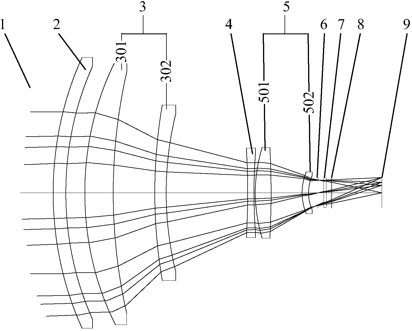
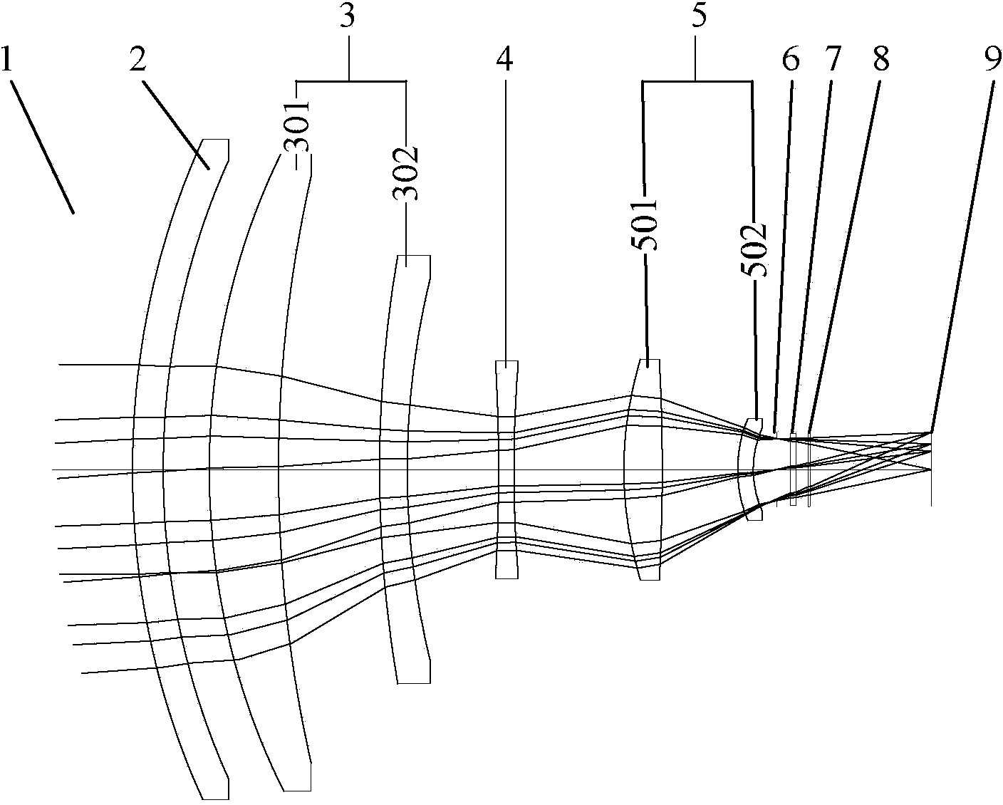
[0021] refer to figure 1 , figure 2 . In the compact dual-field mid-wave infrared athermalization lens described in the following examples, according to the optical compensation zoom principle of the mid-infrared band athermalized dual-field zoom optical system, the total length of the optical system remains unchanged during the change of the focal length . A compact dual field of view medium-wave infrared athermalization lens, from the object plane 1 to the detector focal plane 9, the fixed dome cover 2, the front fixed mirror group 3, the zoom mirror 4 and the rear fixed mirror group 5 are arranged in sequence. Near the detector light window 7, there are also a thermal diaphragm 6 that limits the imaging light be...


PUM


Abstract

The invention provides a compact type double-view-field medium wave infrared athermalization lens. The lens is a one-time imaging lens which is simple in zooming mode, stable in imaging quality and capable of avoiding a heat out-of-focus phenomenon. According to the technical scheme, an infrared optical glass ball cover (2) is arranged between an object plane (1) and a front fixed mirror set (3), the front fixed mirror set is composed of a silicon positive lens and a germanium negative lens, a zooming mirror set (4) which always moves on an optical axis front and back in the zooming process is a biconcave negative lens made of germanium materials, a rear fixed mirror set comprises a biconvex positive lens made of zinc selenide materials and a crescent negative lens made of germanium materials, and the side, close to the object plane, of the biconvex positive lens (501) is an aspheric surface. The ball cover, the front fixed mirror set, the zooming mirror set (4), the rear fixed mirror set and a temperature diaphragm (6) are sequentially arranged through paring combination of the regular lens materials and matching of the linear expansion coefficient alpha L and the length L of lens cone materials, and a complete imaging system is jointly formed.

Description

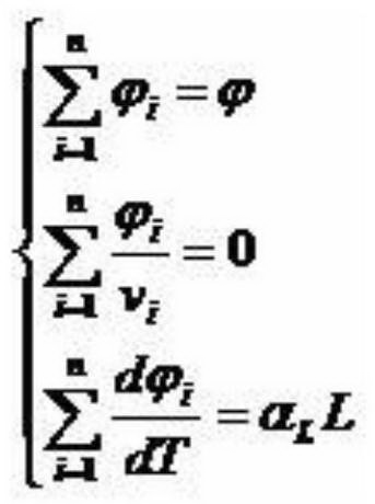
technical field [0001] The invention relates to an adiabatic dual-field zoom optical system mainly used in the mid-wave infrared band. Specifically, the present invention relates to a zoom ratio of two fields of view, which can realize optical passive athermalization difference at -45°C to 60°C, uses optical compensation for double-field zoom and has optical passive athermalization A primary imaging optical system with poor function, especially a primary imaging zoom optical structure suitable for the mid-infrared band. Background technique [0002] When the optical instrument is used in a large temperature range, the thermal expansion and contraction of the lens barrel material, the optical material, and the temperature refractive index coefficient of the optical material will change the focal power of the lens, resulting in defocusing phenomenon, while the heat of the lens barrel material Expansion and contraction will also cause the optical system to defocus and degrade ...

Claims


Application Information

Patent Timeline
IPC IPC(8): G02B15/16G02B7/04G02B1/00
Inventor 邓键安晓强周通童静马欣
Owner SOUTH WEST INST OF TECHN PHYSICS
Learn More