
Slip stream for reliable anode to cathode flow in freeze conditions

An anode, slip flow technology, applied in electrical components, fuel cells, electrochemical generators, etc., can solve problems such as the effect of orifice ice clogging

Active Publication Date: 2014-09-17
GM GLOBAL TECH OPERATIONS LLC
View PDF5 Cites 4 Cited by
  • Summary
  • Abstract
  • Description
  • Claims
  • Application Information

AI Technical Summary

Problems solved by technology

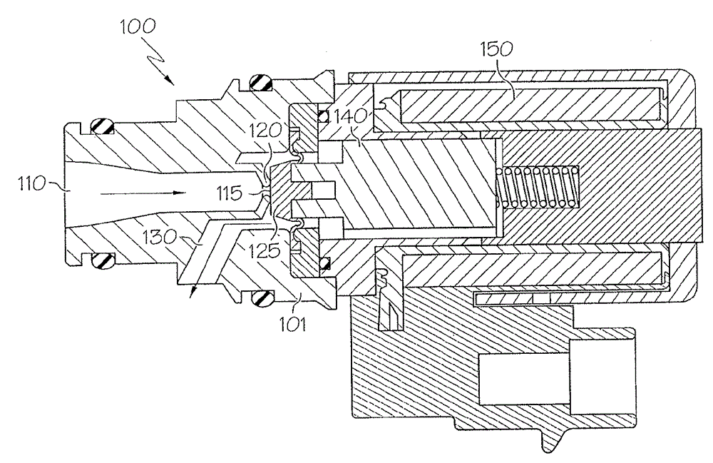
Unfortunately, the size and precision required to establish its flow regulating function also makes the orifice particularly susceptible to various types of ice clogging associated with the remainder of the valve, as described above

Method used


Image

  • Slip stream for reliable anode to cathode flow in freeze conditions
  • Slip stream for reliable anode to cathode flow in freeze conditions
  • Slip stream for reliable anode to cathode flow in freeze conditions

Examples


Embodiment Construction

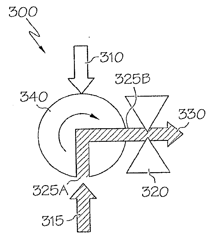
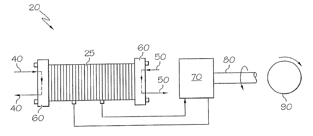
[0052] First refer to Figure 1A to Figure 1C , the vehicle 1 includes a propulsion source in the form of a fuel cell system 10 having one or more fuel cell stacks 20 , the stacks 20 being fueled from one or more fuel tanks 30 . In one form, the fuel is in the form of a hydrogen-based first reactant. The second reactant (eg, an oxygen-based fluid) may be provided from the ambient environment. Either or both reactants may be provided to fuel cell system 10 in pressurized form, such as with a compressor, pump, or related device (not shown). Although not shown, additional sources of propulsion, such as a conventional internal combustion engine (ICE) or a battery pack, may also be utilized to provide hybrid propulsion properties to the vehicle 1 .

[0053] still refer to Figure 1A to Figure 1C , the fuel cell stack 20 is composed of a number of individual fuel cells 25 which in turn are composed of an anode 25A, a cathode 25B and a proton transport membrane 25C. The first ...


PUM


Abstract

The invention relates to a slip stream for a r reliable anode to cathode flow in freeze conditions. A device and a method for ensuring proper fuel cell system warmup or shutdown during freeze conditions are provided. A three-way valve is used in conjunction with a flow-controlling orifice to ensure that the orifice avoids ice blockage during frozen conditions. Dry, warm air is delivered as a slip stream under pressure to a cathode flowpath, where the construction of the orifice is such that it is structurally compliant to promote flexing in response to the pressurized slip stream, thereby helping to break up any small amount of ice that may have formed in or on the orifice.

Description

[0001] Cross References to Related Applications [0002] This application claims the benefit of US Provisional Patent Application Serial No. 61 / 788,655, filed March 15, 2013. technical field [0003] The present application generally relates to an apparatus and method for ensuring proper fuel cell system warm-up or shutdown under freezing conditions. More specifically, the present application relates to a three-way valve used in conjunction with a flow control orifice in order to ensure that the orifice avoids ice clogging in freezing conditions, wherein dry hot air can be delivered under pressure to the cathode in slip flow A flow channel in which the orifice is configured such that it is structurally flexible to facilitate deflection in response to the pressurized slipstream, thereby helping to break up any small amounts of ice that may form in or on the orifice. Background technique [0004] The present invention relates generally to improvements in the operability of fu...

Claims


Application Information

Patent Timeline
IPC IPC(8): H01M8/04
CPCH01M8/04H01M8/04223H01M8/04253H01M8/04268Y02E60/50
Inventor J.K.利里B.J.克林格曼R.J.道姆
Owner GM GLOBAL TECH OPERATIONS LLC
Learn More