Double-edge arc-shaped permanent magnet synchronous motor used for large turntable

A permanent magnet synchronous motor, a large-scale technology, applied to synchronous motors with stationary armatures and rotating magnets, the shape/style/structure of winding conductors, and stationary components of magnetic circuits, etc. It can improve the transmission accuracy and transmission efficiency, reduce the difficulty of processing and transportation, and reduce the local deformation.

Inactive Publication Date: 2014-09-17
INST OF OPTICS & ELECTRONICS - CHINESE ACAD OF SCI
View PDF5 Cites 1 Cited by
  • Summary
  • Abstract
  • Description
  • Claims
  • Application Information

AI Technical Summary

Problems solved by technology

Worm gear transmission is no longer suitable for modern large-scale turntable equipment with higher and higher control requirements; although friction transmission overcomes the Achilles heel of worm gear transmission, poor transmission stiffness, low-speed crawling and slippage are its own Achilles heel, low-speed crawling It will affect the motion stability and transmission accuracy, and the slippage will cause the image of the observation target to shake in the field of view, and in severe cases, the image will drift out of the field of view; gear transmission is similar to worm gear transmission, both of which belong to meshing transmission, and t

Method used


Image

  • Double-edge arc-shaped permanent magnet synchronous motor used for large turntable
  • Double-edge arc-shaped permanent magnet synchronous motor used for large turntable
  • Double-edge arc-shaped permanent magnet synchronous motor used for large turntable

Examples


Embodiment Construction

[0016] In order to make the object, technical solution and advantages of the present invention clearer, the present invention will be described in further detail below in conjunction with specific embodiments and with reference to the accompanying drawings.

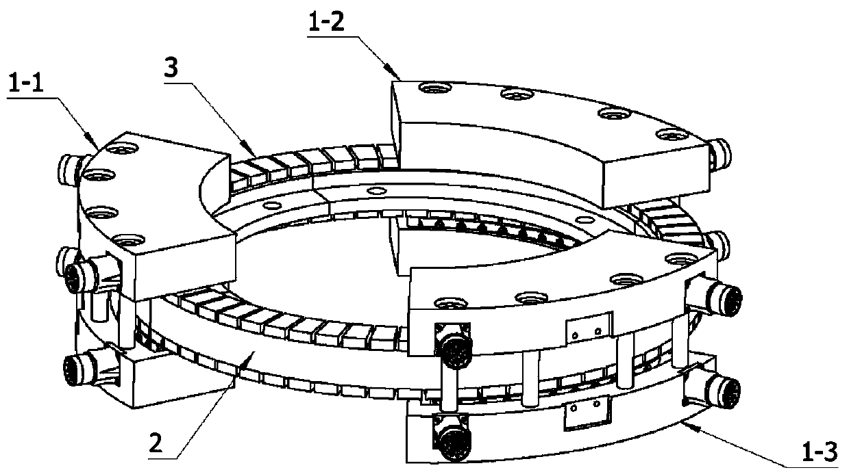
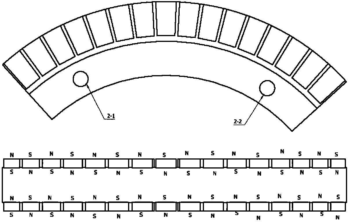
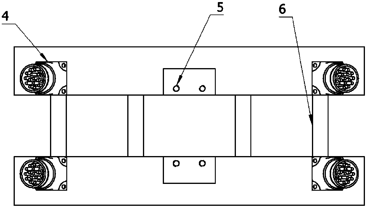
[0017] Such as figure 1 An example overall structure of a double-sided arc-shaped permanent magnet synchronous motor used in a large turntable according to the present invention is shown. The motor is mainly composed of three stator groups 1-1, 1-2, 1-3, and a rotor. Each stator group has exactly the same structural form, consisting of two upper and lower stator parts, and the upper and lower stator groups are connected and positioned by the connecting piece 6 . Such as image 3 , 4 , Each stator group shown in 5 is composed of two identical stator pieces, connecting piece 6, iron core positioning piece 11, coil winding 12, iron core unit 13, and stator shell. refer to Figure 4 , Figure 5 , Figure 7 As shown, the...


PUM

PropertyMeasurementUnit
Remanenceaaaaaaaaaa
Coercivityaaaaaaaaaa
Thicknessaaaaaaaaaa

Abstract

A double-edge arc-shaped permanent magnet synchronous motor used for a large turntable is composed of a plurality of stator sets and a rotor, wherein each stator set is formed by two same upper stator piece and lower stator piece, upper iron core unit and lower iron core unit, upper iron core positioning piece and lower iron core positioning piece, upper coil winding and lower coil winding, upper stator casing and lower stator casing and upper connecting piece and lower connecting piece. The upper stator piece and the lower stator piece are connected and positioned through the connecting pieces. The iron core units are wound with the coil windings, and the iron core units and the coil windings are connected and positioned through the iron core positioning pieces and are fixed to the stator casings in an epoxy pouring mode. Each whole stator set is fixed to a fixed table face of a turntable device with screws through screw holes in the stator casings. The rotor is formed by splicing four same arc-shaped fan-area mechanisms, and each fan-area mechanism is formed by a permanent magnet and a magnet yoke. The upper surface and the lower surface of the magnet yoke are bonded with the permanent magnets respectively. The whole rotor is fixed to the rotating parts of the turntable devices through through-holes in the magnet yokes with screws. The stators are arranged and installed in a staggered mode.

Description

technical field [0001] The invention belongs to the field of motor design and relates to a bilateral arc permanent magnet synchronous motor used for a large turntable. Background technique [0002] The transmission methods adopted by traditional large-scale turntable equipment mainly include: worm gear transmission, gear transmission, friction transmission and torque motor coaxial installation transmission. These traditional transmission methods have played a pivotal role in the development of large-scale turntable equipment, but there are still many shortcomings in these transmission methods, especially with the continuous advancement of science and technology, when developing a new generation of large-scale turntable equipment. The transmission mode is no longer competent. When the worm gear transmission mode is used, the size of the turbine is difficult to make large, and the accuracy of the large-size turbine is difficult to be guaranteed. For large-scale turntable equi...

Claims


Application Information

Patent Timeline
IPC IPC(8): H02K21/14H02K1/16H02K1/18H02K1/27H02K1/28H02K3/28
Inventor 常九健马文礼
Owner INST OF OPTICS & ELECTRONICS - CHINESE ACAD OF SCI
Why Eureka
Try Eureka