Repairing system provided with anchoring device and used for preventing valve regurgitation

An anchoring device and repair system technology, applied in the field of repair systems, can solve the problems of inability to achieve simple operation and firm fixation, difficulty in accurate positioning and fixation of products, insufficient adaptability to lesions, etc., and achieve low complications and wide application range. , the effect of less implants

Active Publication Date: 2014-09-24
NINGBO JENSCARE BIOTECHNOLOGY CO LTD
View PDF9 Cites 39 Cited by
  • Summary
  • Abstract
  • Description
  • Claims
  • Application Information

AI Technical Summary

Problems solved by technology

The main reason is that the mitral valve ring and tricuspid valve ring have special physiological structures, and there is a complex physiological environment below the valve ring, making it very difficult to accurately position and fix the product
In addition, the degree and location of valve prolapse are different. For example, some patients have regurgitation caused by posterior valve prolapse, and some patients have regurgitation caused by combined valve disease. It also interferes with the physiological structure of the remaining normal mitral valve, and the adaptability of the lesion is insufficient, and the above-mentioned anchoring technology cannot meet the standards of easy operation and firm fixation. In summary, although the above-described technology is in the There are certain effects on valve repair respectively, but in the field of surgery for treating valvular insufficiency, there is an urgent need for a device with adjustable position, accurate positioning, good cooperation with instruments during anchoring, easy operation, and ability to cope with various types of valves. Extent and location of lesion technique

Method used


Image

  • Repairing system provided with anchoring device and used for preventing valve regurgitation
  • Repairing system provided with anchoring device and used for preventing valve regurgitation
  • Repairing system provided with anchoring device and used for preventing valve regurgitation

Examples


specific Embodiment 1

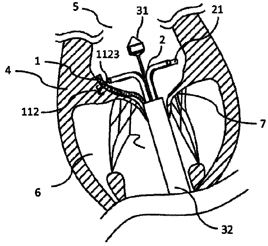
[0062] Such as Figure 1a As shown, a repair system for preventing valvular regurgitation with an anchoring device, including a prosthesis 1 for preventing valvular regurgitation, four sets of anchor release devices 2 and a delivery system 3, used to treat posterior mitral valve Partial prolapse of valve.

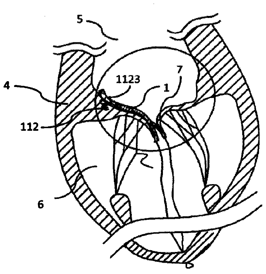
[0063] Such as Figure 2a-2b As shown, the prosthesis 1 for preventing valvular regurgitation includes a fixing unit 11 , a connecting piece 12 and an auxiliary piece 13 . The fixing unit 11 includes a fixing piece 111 and two anchoring pieces 112. The fixing piece 111 is fixed on the patient's own tissue 4 through the anchoring piece 112. In this embodiment, only two adjacent sets The anchor release device 2 is loaded with the anchor 112, and the release device 2 without the anchor 112 is used as a support device, and its distal part is pressed against the patient's own tissue after being released, giving the whole set of the release device 2 supporting force, so that s...

specific Embodiment 2

[0066] Such as Figures 4a-4c As shown, a repair system for preventing valvular regurgitation with an anchoring device, including a prosthesis 1 for preventing valvular regurgitation, two sets of anchor release devices 2, a delivery system 3 and two sets of support devices 8, used For the treatment of partial anterior mitral valve prolapse.

[0067] Such as Figure 4a As shown, the prosthesis 1 for preventing valvular regurgitation includes a fixing unit 11 , a connecting piece 12 and an auxiliary piece 13 . The fixing unit 11 includes a fixing piece and two anchoring pieces 112. In this embodiment, the fixing piece and the anchoring pieces 112 are integrated, and the fixing piece is fixed by the anchoring piece 112. On the patient's own tissue, after the fixation unit 11 is deployed, the width between the two anchors 112 is equal to 1 / 4 of the circumference of the valve tissue ring; Memory alloy nickel-titanium wire is wound and preheated and formed. Both sides of the conn...

specific Embodiment 3

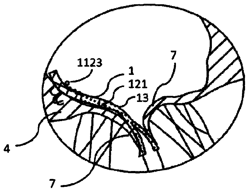
[0070] Such as Figures 5a-5g As shown, the prosthesis 1 for preventing valvular regurgitation includes a fixing unit 11, a connecting member 12 and an auxiliary member 13. The fixing unit 11 includes a fixing member 111 and an anchoring member 112, which is different from the complete ring in the prior art. shaped structure product, the fixed unit 11 can adjust the position along the circumference of the patient's valve annulus after deployment, such as the joint valve position ( Figure 5a ), the position of the anterior valve leaflet ( Figure 5b ) or posterior leaflet position ( Figure 5c ), until the operator judges the most suitable position for preventing reflux according to the fit between the closing aid 13 and its own valve leaflet 7, and then performs anchoring and positioning, releases the anchoring member 112, and realizes the The fixation between the prosthesis 1 and the autologous tissue 4 truly realizes the accurate treatment of lesions while retaining the n...


PUM


Abstract

The invention relates to a repairing system provided with an anchoring device and used for preventing valve regurgitation. The system comprises a prosthesis preventing valve regurgitation and an anchoring part releasing device, wherein the prosthesis preventing valve regurgitation comprises a fixing unit, a connecting part and a close-assisting part, the fixing unit comprises a fixing part and an anchoring part, the connecting part is flexible, and the fixing part is fixed through the anchoring part, an anti-disengagement end is arranged at the near end of the anchoring part; the anchoring part releasing device comprises a delivery pipe and a push rod and is detachably connected with the fixing unit, the far end of the anchoring part releasing device is in a preset shape to enable the far end of the delivery pipe to be bent integrally or partially, a rigid section is arranged at the farthest end of the delivery pipe, the anchoring part is pre-arranged in the far end of the delivery pipe, the push rod is placed in the delivery pipe and located at the near end of the anchoring part, the anchoring part can be made to move towards the far end of the delivery pipe by pushing the push rod, and the far end of the anchoring part can recover to the preset shape after being pushed out of the delivery pipe.

Description

Technical field: [0001] The invention belongs to the field of medical devices, in particular to a repair system with an anchoring device for preventing valve regurgitation. Background technique: [0002] The mitral valve is located at the left atrioventricular orifice and consists of five parts: the valve annulus, valve leaflets, chordae, papillary muscles, and junctional junction. Its anatomically accurate name is mitral apparatus (mitral apparatus) or mitral valve compound body (mitral complex). [0003] The tricuspid valve is located at the right atrioventricular orifice and has three approximately triangular sail-shaped valves. The bottom of the valve is attached to the fibrous annulus of the atrioventricular orifice. Functionally, the fibrous annulus, valves, chordae and papillary muscles can be seen. It is a tricuspid valve. Valve complex (tricuspid valvar complex). [0004] Mitral regurgitation (mitral regurgitation) can be divided into the following three types: fu...

Claims


Application Information

Patent Timeline
Patent Type & Authority Applications(China)
IPC IPC(8): A61F2/24
CPCA61F2/2457A61F2/2463
Inventor 李佳楠吕世文徐志云李毅斌陈志
Owner NINGBO JENSCARE BIOTECHNOLOGY CO LTD
Why Eureka
Try Eureka