
Device for drying a workpiece and method for operating such a device

A technology for drying and workpieces, which is applied in the field of drying vehicle body-device, which can solve the problems such as the deterioration of painted surface quality

Active Publication Date: 2014-09-24
VOLKSWAGEN AG
View PDF13 Cites 11 Cited by
  • Summary
  • Abstract
  • Description
  • Claims
  • Application Information

AI Technical Summary

Problems solved by technology

Mixing or process temperatures that are too high can lead to at least local degradation of the painted surface

Method used


Image

  • Device for drying a workpiece and method for operating such a device
  • Device for drying a workpiece and method for operating such a device

Examples


Embodiment Construction

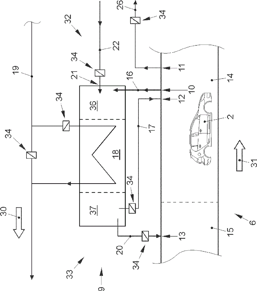
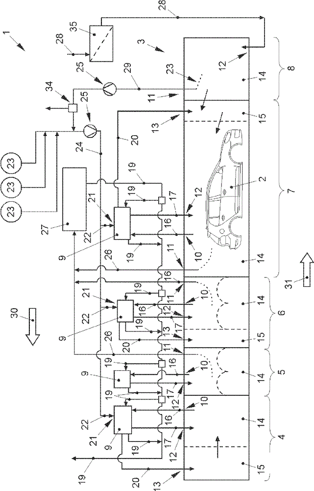
[0073] figure 1 A first embodiment of a device 1 for drying workpieces 2 is shown. The workpiece 2 is a vehicle body in the embodiment shown in the figures. The device 1 comprises a drying tunnel 3 comprising a plurality of tunnel sections 4 , 5 , 6 , 7 , 8 .

[0074] Some of the channel sections 4, 5, 6, 7 are associated with circulating air heaters 9 and each of the channel sections 4, 5, 6, 7, 8 comprises at least one air outlet 10, 11 and at least one air outlet Entrance 12,13. The air in the process chambers 14 of the channel sections 4 , 5 , 6 , 7 is circulated and heated in the circulating air heater 9 . The circulating air is fed from the air outlet 10 as chamber exhaust air 16 to the circulating air heater 9 and is then returned as chamber supply air 17 via the air inlet 12 into the process chamber 14 .

[0075] Each recirculating air heater 9 is included in the figure 2 A heat exchanger 18 is shown in , in which heat energy can be transferred from the hot prima...


PUM


Abstract

The invention relates to a device for drying a workpiece and a method for operating such a device. The device has multiple tunnel portions comprising an air outlet and an air inlet and attached with a circulating air heating unit. Chamber exhaust air is supplied to the circulating air heating unit, the air circulating heating unit is provided with a heat exchanger, heat energy can be transmitted to the chamber supply air from primary air in the circulating air heating unit, the chamber supply gas can be transmitted tunnel portions through the air inlet, the circulating air heating unit comprises a fresh air intake and a mixing device, the fresh air is supplied to the circulating air heating unit through the fresh air intake, and the mixing device is used for mixing the fresh air with the chamber exhaust air. In the method for operating the device, before the fresh air supplied to independent tunnel portions is introduced to the tunnel portions, the fresh air is mixed with the chamber exhaust air to form the chamber supply air through the circulating air heating unit of the tunnel portions so that air exchange can be changeably adjusted.

Description

technical field [0001] The invention relates to a device for drying workpieces, in particular for drying vehicle bodies, with a drying tunnel comprising a plurality of tunnel sections, wherein each of the tunnel sections comprises at least one air outlet and at least one air inlet, and some of the channel sections are associated with a circulating air heater for which chamber exhaust air can be delivered from at least one air outlet of the channel section, and each circulating air heater A heat exchanger is included in which heat energy can be transferred from the hot primary air to chamber supply air which can be fed to the channel section via at least one air inlet. [0002] Furthermore, the invention relates to a method for operating such a device. Background technique [0003] A device of the mentioned type is known from document DE 10 2010 006 550 A1. This document shows a device of this type for drying objects, in particular vehicle bodies, in which a recirculation a...

Claims


Application Information

Patent Timeline
IPC IPC(8): B05D3/04B05D3/00
CPCF26B23/002F26B2210/12F26B23/022F26B15/12Y02P70/10
Inventor E.格拉泽G.萨博
Owner VOLKSWAGEN AG
Learn More