Pneumatic manipulator processing equipment

A technology of pneumatic manipulators and processing equipment, applied in metal processing equipment, turning equipment, metal processing, etc., can solve the problems of troublesome feeding process of pneumatic manipulators, elongated workpiece processing process, and low production efficiency, so as to improve production efficiency, The effect of shortening the processing process and high feeding efficiency

Active Publication Date: 2014-09-24
宁波宫铁智能科技有限公司
View PDF9 Cites 8 Cited by
  • Summary
  • Abstract
  • Description
  • Claims
  • Application Information

AI Technical Summary

Problems solved by technology

[0003] At present, pneumatic manipulators are also widely used on lathes and machine tools in various automated production lines. These lathes or machine tools are often equipped with feeding devices for feeding and receiving devices for unloading. The device cooperates with the pneumatic manipulator to form a complete set of pneumatic manipulator processing device, which makes the automatic production line more convenient and fast. However, the existing pneumatic manipulator processing device has the following problems: 1. In the existing pneumatic manipulator processing device, due to When feeding, the feeding device is located under the pneumatic manipulator, and the workpiece is located in the groove for storing the workpiece on the feeding device. When the pneumatic manipulator clamps the workpiece, it must move upwards to make the workpiece move out of the feeding device, and the feeding device can return to the initial position. , the pneumatic manipulator has space to continue to move down and send the workpiece to the processing end for fixation, and such repeated actions of the pneumatic manipulator not only greatly increase the stroke and energy consumption of the pneumatic manipulator, but also make the process of feeding the pneumatic manipulator more troublesome, resulting in pneumatic The efficiency of manipulator feeding is reduced, which lengthens the entire processing process of the workpiece, and the production efficiency is low; 2. The existing material receiving device is composed of a receiving tray and a feeding chute. When unloading, the receiving tray is on the feeding chute Moving to its rear end, a large inertia will be generated during the movement. When the receiving tray moves to the predetermined position and stops, the workpiece on the receiving tray will fall to the storage box with a force greater than itself under the inertia During the process, the falling workpiece and the workpiece in the storage box will have a large impact, causing the two workpieces to be hard hit and damaged at the same time, greatly affecting the quality of the workpiece, and the receiving tray is open, and the workpiece falls directly after processing. It enters the receiving tray and automatically slides into a fixed position. Generally, the workpiece is higher than the receiving tray. When the workpiece falls on the receiving tray, the workpiece and the trough will have a hard impact, which will not only easily damage the processed workpiece, but also affect the workpiece. quality, and will cause the deformation of the receiving tray, causing friction between the bottom of the receiving tray and the feeding trough, causing the receiving tray to fail to move normally on the feeding trough, or causing the workpiece to jump out of the receiving tray, affecting the normal collection of the workpiece; 3. The workpiece is processed by the tool under the high-speed rotating processing end, or processed by the high-speed rotating tool. In order to prevent large dust during processing, the processing part is generally watered during processing. Because the pneumatic manipulator and the processing end and the feeding The distance between the devices is relatively close, and the high-speed rotating processing end or tool will cause debris generated during processing and water stains from watering to splash on the pneumatic manipulator and feeding device, causing pollution to the pneumatic manipulator, feeding device and the entire processing environment. If the stain is splashed on the pneumatic manipulator and the feeding device, if it is not treated for a long time, the surface of the two will be rusted, and even some circuits on the pneumatic manipulator and the feeding device will be short-circuited, and many movable joints on the pneumatic manipulator and the feeding device will be damaged. There are gaps, debris splashing into these gaps will block the operation of the pneumatic manipulator and the feeding device, resulting in the failure of the pneumatic manipulator and the feeding device to work normally, greatly affecting the normal production of the lathe or machine tool, and cleaning will increase the corresponding cost

Method used


Image

  • Pneumatic manipulator processing equipment
  • Pneumatic manipulator processing equipment
  • Pneumatic manipulator processing equipment

Examples


Embodiment Construction

[0038] The following are specific embodiments of the present invention and in conjunction with the accompanying drawings, the technical solutions of the present invention are further described, but the present invention is not limited to these embodiments.

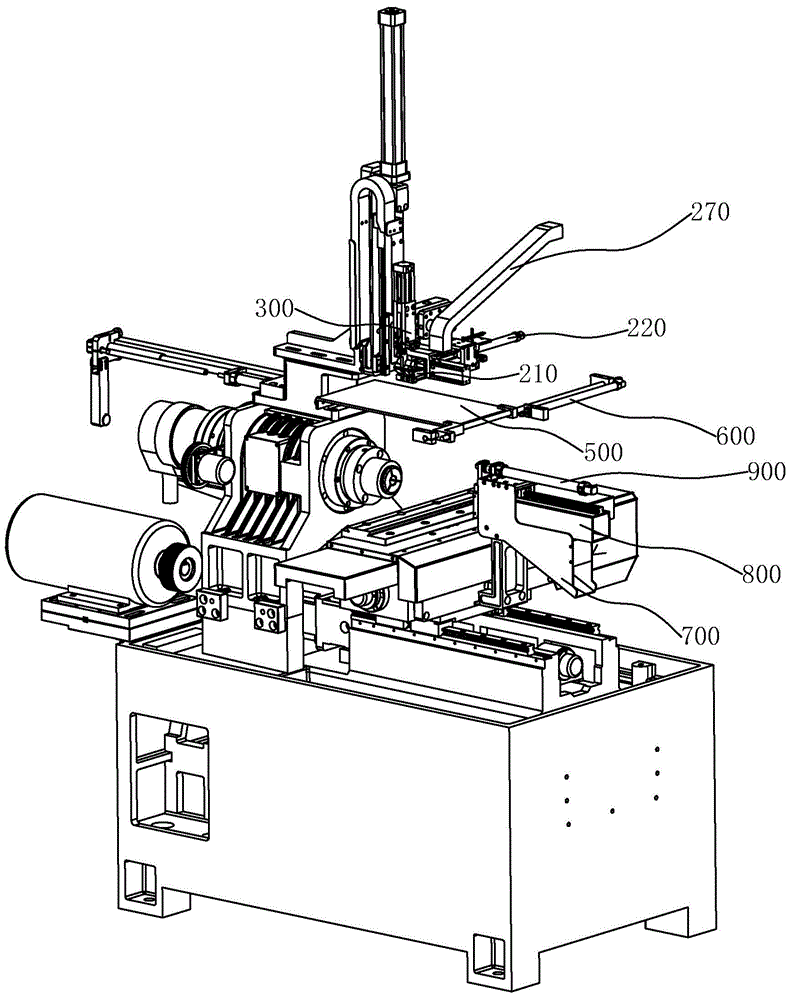
[0039] In the present invention, for easy understanding, the moving direction of the feeding device is horizontal, and the moving direction of the receiving device is axial.

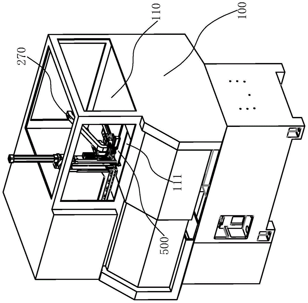
[0040] Such as Figure 1 to Figure 4 As shown, a pneumatic manipulator processing equipment of the present invention is installed on a frame, and a hood 100 is provided on the frame, and a cavity is formed between the hood 100 and the frame, and a branch is installed horizontally in the hood 100. The partition 110 and the partition 110 divide the cavity into an upper cavity and a lower cavity. This equipment includes

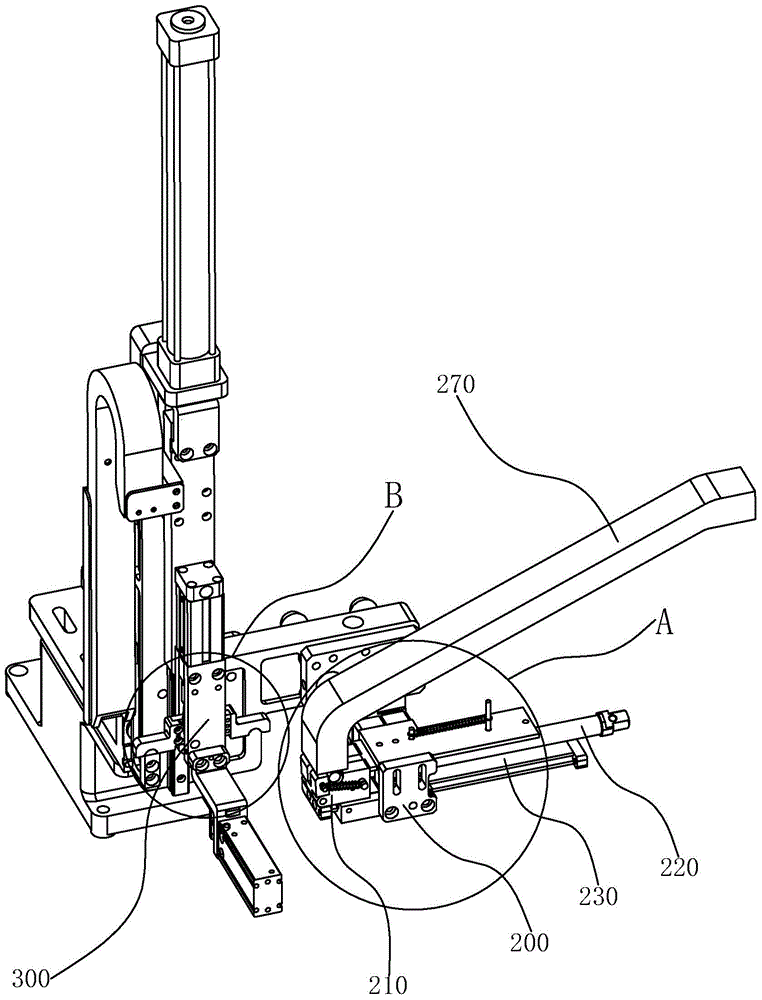
[0041] The feeding device, which is located in the upper cavity, includes a fixed seat 200 horizontally installed on one side of the...


PUM


Abstract

The invention provides pneumatic manipulator processing equipment and belongs to the technical field of automatic lathes; the technical problems that a pneumatic manipulator in a traditional lathe is long in stroke, workpieces are easy to damage during material receiving and discharging, and chippings and water spots generated by processing are easy to splash to a feeding end are solved by the pneumatic manipulator processing equipment provided by the invention. The pneumatic manipulator processing equipment is arranged on a rack, and comprises a feeding device, a protection device and a material receiving device, wherein the feeding device is provided with a permanent seat and a feeding assembly; the protection device is provided with a guide rod and a protection plate; the material receiving device is provided with a feed cover frame and a feed pipe; a holding tank is formed in the feeding assembly, and moreover, when the feeding assembly moves, the workpieces can be shifted from the holding tank; the rack is provided with a processing end and a feeding end; the protection device can be moved to a position between the processing end and the feeding end, and the processing end and the feeding end are separated; a notch is formed in the bottom part of the feed pipe, and a material receiving plate hinged to the feed pipe is arranged in the notch; a rolling shaft is arranged in the feed cover frame, and the rear end of the material receiving plate is put on the rolling shaft. The stroke of the pneumatic manipulator is shortened, the safety and the cleanness of the feeding end are protected, and the damage to the workpieces is smaller.

Description

technical field [0001] The invention belongs to the technical field of automatic lathes, and relates to a processing device, in particular to a pneumatic manipulator processing device. Background technique [0002] Pneumatic manipulator is an automatic operation device that can imitate certain actions and functions of human hands and arms to grab, carry objects or operate tools according to a fixed program. It can replace human heavy labor to realize mechanization and automation of production, and reduce human labor. Labor intensity, save production cost. [0003] At present, pneumatic manipulators are also widely used on lathes and machine tools in various automated production lines. These lathes or machine tools are often equipped with feeding devices for feeding and receiving devices for unloading. The device cooperates with the pneumatic manipulator to form a complete set of pneumatic manipulator processing device, which makes the automatic production line more convenie...

Claims


Application Information

Patent Timeline
Patent Type & Authority Applications(China)
IPC IPC(8): B23B15/00B23B25/04
CPCB23B25/04B23Q7/00
Inventor 杨云林
Owner 宁波宫铁智能科技有限公司
Why Eureka
Try Eureka