Intelligent hydraulic suspension unit and control method thereof

A hydraulic suspension, intelligent technology, applied in the direction of suspension, elastic suspension, interconnection system, etc., can solve the problem of detection of inoperable state, failure of sealing ring buffer mechanism, fatigue failure of cylinder and piston, wear failure, poor control characteristics, etc. question

Active Publication Date: 2014-09-24
刘胜
View PDF4 Cites 17 Cited by
  • Summary
  • Abstract
  • Description
  • Claims
  • Application Information

AI Technical Summary

Problems solved by technology

The stiffness and damping coefficient of the passive suspension are designed according to experience, which has great limitations. The active suspension performs dynamic self-adaptive adjustment according to the changes of road conditions and vehicle motion state, so that the suspension is in the optimal motion state, but there is energy consumption big disadvantage
Semi-active suspension only considers changing the damping of the suspension, and hardly consumes vehicle power, but its control characteristics are poor. When the road condition is poor, the suspension cannot be guaranteed to be in an optimal motion state....

Method used


Image

  • Intelligent hydraulic suspension unit and control method thereof
  • Intelligent hydraulic suspension unit and control method thereof
  • Intelligent hydraulic suspension unit and control method thereof

Examples


Embodiment 1

[0046] Embodiments of the present invention are further described below in conjunction with the accompanying drawings:

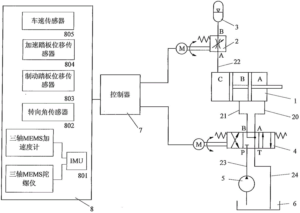
[0047] The schematic diagram of the structure of the hydraulic suspension unit of the present invention is as follows: figure 1 As shown, it consists of a hydraulic cylinder 1, a digital throttle valve 2, an accumulator 3, a digital directional valve 4, a hydraulic pump 5, an oil tank 6, a controller 7 and a motion parameter detection module 8.

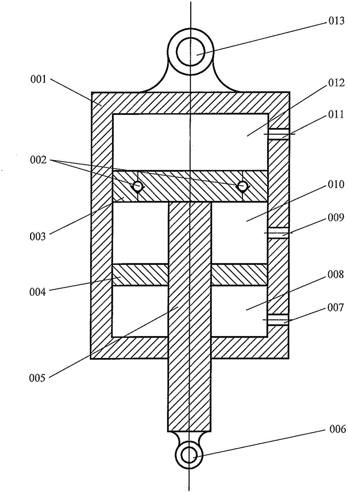
[0048] Schematic diagram of the hydraulic cylinder figure 2 As shown, cylinder 001 is cylindrical, and pistons 003 and 004 divide the cylinder into chamber A 008, chamber B 010 and chamber C 012. Each chamber communicates with the external oil circuit through port 007, port 009 and port 011 Connected, the piston rod 005 rigidly connects the two pistons, the piston 003 is equipped with check valves 002 evenly distributed along the circumferential direction, so that the oil in the B chamber 010 can enter the C chamb...

Embodiment 2

[0097] Embodiment 2 is the same as Embodiment 1, except that the suspension unit is in the active working mode, and each suspension unit is interconnected and controlled. The schematic diagram of the active interconnected suspension system is as follows Figure 6 As shown, the digital directional valve 104 is also shared at this time, and the controller outputs the digital directional valve 104 control signal:

[0098] The interconnection form realizes the interconnection between the hydraulic cylinders of each suspension unit by configuring the oil passages between the four suspension units, so that the oil passages of the compressed chambers are connected and the oil passages of the stretched chambers are connected. The oil passages are configured through a general electromagnetic Reversing valves 501, 502 and 503 are implemented. When the three-position and four-way electromagnetic reversing valve is in the neutral position, the valve ports are connected to each other. The e...


PUM


Abstract

The invention discloses an intelligent hydraulic suspension unit and a control method thereof. The intelligent hydraulic suspension unit comprises a hydraulic cylinder, a digital throttling valve, an energy accumulator, a detection module, a controller, a hydraulic pump and an oil tank, wherein the hydraulic cylinder adopts a three-cavity dual-piston single-piston-rod structure, a cylinder body of the hydraulic cylinder is connected with a frame through a frame support, a piston rod of the hydraulic cylinder is connected with wheels through a wheel support, the digital throttling valve and the energy accumulator are configured to realize semi-active control, and a digital directional valve, the hydraulic pump and the oil tank are configured to realize active control. The controller realizes semi-active control through damping control and realizes active control through force and displacement compound control. The intelligent hydraulic suspension unit and the control method thereof have the advantages that the semi-active control and the active control on the suspension unit are realized through intelligent control, a hydraulic medium, wear-out and creeping phenomena of a sealing ring of the hydraulic cylinder, failure of a buffer mechanism as well as fatigue failure and wear-out failure of the piston and the cylinder body are effectively monitored, the operation state of the hydraulic cylinder is judged actively, the service life of the hydraulic cylinder is prolonged, the reliability of the hydraulic cylinder is improved, and the intellectualization of a hydraulic suspension is realized.

Description

technical field [0001] The invention relates to a vehicle structure assembly, in particular to an intelligent hydraulic suspension unit and a control method thereof. Background technique [0002] Suspension is the general term for all force transmission connection devices between the frame and the wheels. It is an important part of the car. The torque is transmitted to the frame to ensure the normal driving of the car. The performance of the suspension device directly affects the driving safety of the car, and rollover accidents have become one of the reasons for serious traffic accidents. [0003] According to the correlation between damping and stiffness and vehicle driving conditions, suspension can be divided into passive suspension, semi-active suspension and active suspension. The stiffness and damping coefficient of the passive suspension are designed according to experience, which has great limitations. The active suspension performs dynamic self-adaptive adjustmen...

Claims


Application Information

Patent Timeline
IPC IPC(8): B60G17/015
CPCB60G2202/413B60G21/08B60G21/073B60G21/067B60G11/265B60G2202/154
Inventor 郭醒张生志刘胜王小平
Owner 刘胜
Why Eureka
Try Eureka