
Unmanned plane electro-optical pod

A technology of photoelectric pods and unmanned aerial vehicles, applied in the field of photoelectric pods, can solve the problems that the configuration of sensors is difficult to meet the task requirements of power line inspection means, the poor recognition ability of pods, and the weight of photoelectric pods, etc., to achieve convenience Maintenance or replacement of internal sensors, compact structure, and simple electrical interface

Active Publication Date: 2014-09-24
武汉华中天经通视科技有限公司
View PDF8 Cites 28 Cited by
  • Summary
  • Abstract
  • Description
  • Claims
  • Application Information

AI Technical Summary

Problems solved by technology

[0003] However, restricted by factors such as unmanned aerial vehicles and their task loads, the use of unmanned aerial vehicles to inspect power lines is still in its infancy, and there are the following problems: 1. The existing photoelectric pods are mainly used for manned helicopters. During the line inspection demonstration, the photoelectric pods generally have defects such as heavy weight, high power consumption, and fixed configuration, which make it difficult to mount them on drones; 2. The pods have poor recognition capabilities and limited operating distances, making it difficult to meet the needs of domestic power industry users; 3. The function is single, and it is difficult to configure the sensor to meet the task requirements of multiple detection methods for power line inspection

Method used


Image

  • Unmanned plane electro-optical pod
  • Unmanned plane electro-optical pod
  • Unmanned plane electro-optical pod

Examples


Embodiment

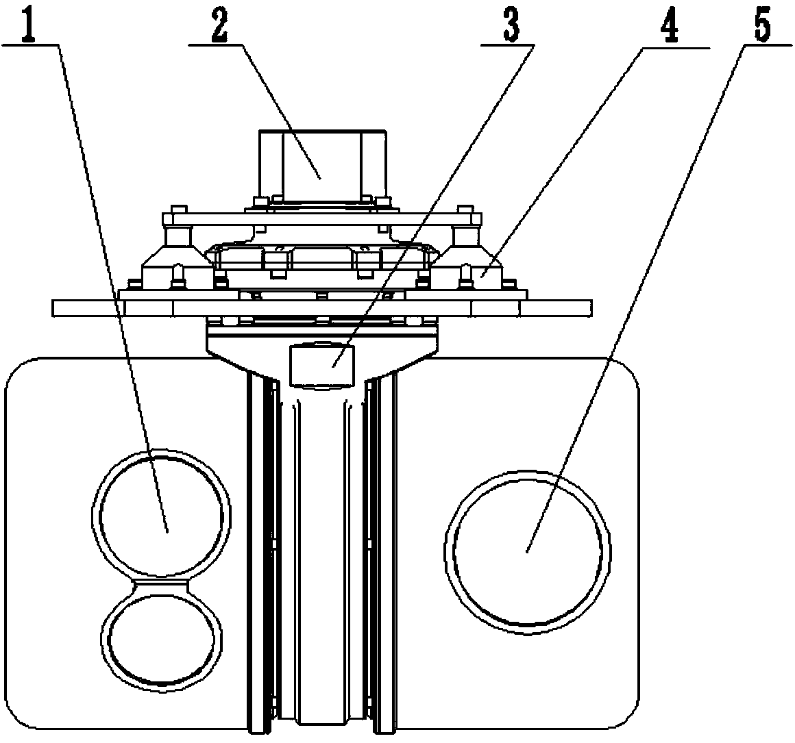
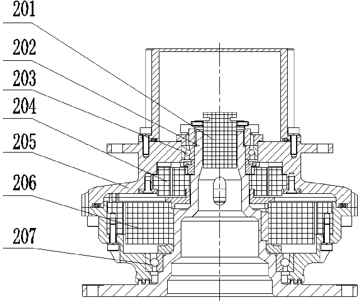
[0024] see figure 1 , an unmanned aerial vehicle photoelectric pod, comprising: a pod stable platform fixed on the unmanned aerial vehicle through a shock absorber assembly 4, a sensor assembly 1 for monitoring the field environment that is fixed on the pod stable platform and is connected to each other An azimuth component 2 for realizing azimuth driving and azimuth measurement, a pitch component 3 for realizing pitch driving and angle measurement, and a camera component 5 fixed on the pitch component 3 .

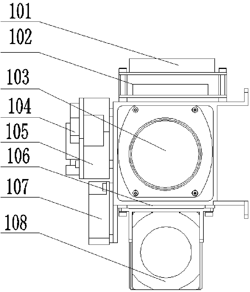
[0025] Such as figure 2 As shown, the sensor assembly 1 includes: a servo drive board 101 installed on the sensor bracket 106 for outputting motor drive signals, and used for measuring the azimuth deviation of the center of mass of the inspection target relative to the camera assembly 5 and the center of sight of the sensor assembly 1 and pitch deviation image board 102, uncooled temperature-measuring infrared thermal imager 103, goniometer board 104, system control boar...


PUM


Abstract

The invention relates to an electro-optical pod mainly used in the field of electric power line routing inspection, in particular to an unmanned plane electro-optical pod. The unmanned plane electro-optical pod comprises a pod stabilizing platform, sensor assemblies, an azimuth assembly, a pitching assembly and a camera assembly, wherein the pod stabilizing platform is fixedly arranged on an unmanned plane through a shock absorption frame assembly, the sensor assemblies are fixedly arranged on the pod stabilizing platform, are mutually connected and are used for monitoring in-site environment, the azimuth assembly is used for realizing azimuth driving and azimuth measurement, the pitching assembly is used for realizing pitching driving and angle measurement, and the camera assembly is fixedly arranged on the pitching assembly. Therefore the unmanned plane electro-optical pod has the following advantages that 1, various detection measures are combined, and the searching, monitoring and detail identification capability of an unmanned plane line inspection system is improved; 2, the integration degree is high, the structure is compact, the environment adaptability and the load loading adaptability are high, and the upgrading regeneration and the function expansion can be convenient; 3, an external electric interface is simple, the inside of the pod can be opened, and inner sensors can be conveniently maintained or replaced; 4, the stepping photo taking functions are realized, and the fully covering automatic photo shooting on specific regions can be completed.

Description

technical field [0001] The invention relates to a photoelectric pod, which is mainly used in the field of power line inspection, and in particular to an unmanned aerial vehicle photoelectric pod. Background technique [0002] In the field of power line inspection, drones are used to conduct daily inspections of power lines in areas such as mountains, canyons, forests, and rivers that are difficult for people to reach. and after various serious natural disasters, drones can be used to fly into the accident area for monitoring at the first time, and complete tasks such as power emergency handling, power emergency repair, and power cable pulling, so as to win emergency repair time and reduce Disaster loss. [0003] However, restricted by factors such as unmanned aerial vehicles and their task loads, the use of unmanned aerial vehicles to inspect power lines is still in its infancy, and there are the following problems: 1. The existing photoelectric pods are mainly used for man...

Claims


Application Information

Patent Timeline
IPC IPC(8): B64D47/00B64D47/08
Inventor 王波张建民李平刘和平李伦平
Owner 武汉华中天经通视科技有限公司
Learn More