U-shaped steel-concrete composite section beam and construction method of section beam

A technology of combining sections and concrete beams, applied in the direction of load-bearing elongated structural components, structural elements, building components, etc., can solve the problems of poor corrosion resistance, long construction period, poor fire resistance, etc., and achieve high processing quality. Guaranteed, easy on-site construction, and accelerated construction period

Active Publication Date: 2014-09-24
浙江东南网架股份有限公司
View PDF5 Cites 16 Cited by
  • Summary
  • Abstract
  • Description
  • Claims
  • Application Information

AI Technical Summary

Problems solved by technology

[0002] Reinforced concrete beams are the traditional main force-bearing components of house construction, with the characteristics of large cross-section, self-heavy weight and long construction period; steel structure beams have the characteristics of high strength, good seismic performance, light weight, recyclable utilization, and convenient construction. It also has the disadvantages of poor fire resistance and poor corrosion resistance; the steel-concrete composite beam can take advantage of

Method used


Image

  • U-shaped steel-concrete composite section beam and construction method of section beam
  • U-shaped steel-concrete composite section beam and construction method of section beam
  • U-shaped steel-concrete composite section beam and construction method of section beam

Examples


Embodiment 1

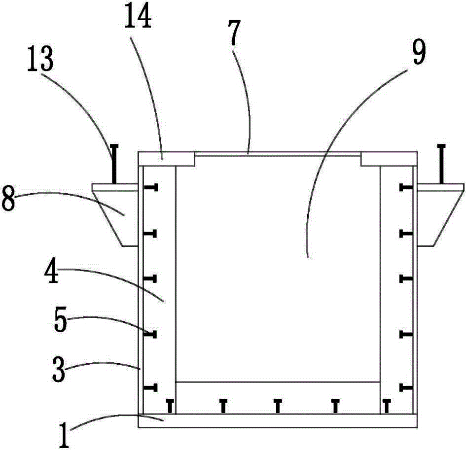
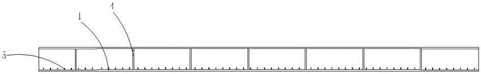
[0028] Embodiment 1: as figure 1 , figure 2 , image 3 , Figure 4 and Figure 5 As shown, a U-shaped steel-concrete composite cross-section beam includes a base plate 1 and a concrete beam 2, and webs 3 are respectively provided on both sides of the upper part of the base plate 1, and the inner wall of the web 3 is connected to the bottom plate 1. The upper part is provided with uniformly distributed transverse stiffeners 4 and shear studs 5 respectively, and the left and right ends of the upper part of the web 3 are respectively provided with a support section slotted top plate 6, and two support section slotted top plates 6 There are evenly distributed embossed plates 7 between them, the outer wall of the web 3 is provided with supporting corbels 8, the upper end of the web 3, the grooved top plate 6 of the support section and the embossed plate 7 are inserted into the concrete In the beam 2, the bottom plate 1, the web plate 3, the grooved top plate 6 of the support s...


PUM


Abstract

The invention relates to a section beam and in particular relates to a U-shaped steel-concrete composite section beam and a construction method of the section beam. The U-shaped steel-concrete composite section beam is used in the field of steel structure housing construction engineering. Web plates are respectively arranged at two side ends of the upper part of a base plate, wherein transverse stiffening plates and anti-shearing toggle pins are uniformly distributed and respectively arranged at the inner walls of the web plates and the upper part of the base plate; support section slotting top plates are arranged at the left ends and the right ends of the upper parts of the web plates; vertical battening plates are uniformly distributed between the two support section slotting top plates; support brackets are arranged on the outer walls of the web plates; the upper ends of the web plates, the support section slotting top plates and the vertical battening plates are inserted into a concrete beam; a grouting cavity is formed by the base plate, the web plates, the support section slotting top plates and the vertical battening plates; concrete is added into the grouting cavity. The construction method of the section beam comprises the following steps: manufacturing and processing the section beam in a factory, mounting and constructing the section beam in a field. According to the U-shaped steel-concrete composite section beam and the construction method of the section beam, the U-shaped steel-concrete composite section beam is compact in structure, capable of forming a complete set of industrial, assembling and mechanical processing, guaranteeing the processing quality and accelerating the construction period, easy and convenient in field construction and high in assembly degree.

Description

technical field [0001] The invention relates to a section beam, in particular to a U-shaped steel-concrete composite section beam and a construction method thereof, which are applied in the field of steel structure house construction engineering. Background technique [0002] Reinforced concrete beams are the traditional main force-bearing components of building construction, and have the characteristics of large cross-section, self-heavy weight and long construction period; steel structure beams have the characteristics of high strength, good seismic performance, light weight, recyclable utilization, and convenient construction. It also has the disadvantages of poor fire performance and poor corrosion resistance; the steel-concrete composite beam can take advantage of the advantages of the steel structure and the concrete structure, and increase the strength of the component and improve the ductility of the component under the same amount of steel. It has been widely used t...

Claims


Application Information

Patent Timeline
IPC IPC(8): E04C3/293
Inventor 周观根程志敏李国强关巧英项旭夏振远周立钢
Owner 浙江东南网架股份有限公司
Why Eureka
Try Eureka