Steel plate beam bridge face outer deformation full size fatigue test loading device

A technology of fatigue test and loading device, which is applied in the direction of measuring device, using stable tension/pressure testing material strength, instruments, etc., to achieve the effect of wide application range, simple structure and good test stability

Active Publication Date: 2014-09-24
CHANGAN UNIV
View PDF6 Cites 11 Cited by
  • Summary
  • Abstract
  • Description
  • Claims
  • Application Information

AI Technical Summary

Problems solved by technology

[0004] The technical problem to be solved by the present invention is to overcome the shortcomings of the above-mentioned steel bridge web gap out-of-plane deformation fatigue test device, and provide a test device with reasonable structure, simple structure, accurate test data, easy adjustment of loading parameters, wide application range, and easy replacement of the test device. A full-scale fatigue test loading device for steel plate girder bridge out-of-plane deformation that can simulate the force characteristics of the steel plate girder bridge web gap under the joint action of in-plane bending moment and out-of-plane deformation

Method used


Image

  • Steel plate beam bridge face outer deformation full size fatigue test loading device
  • Steel plate beam bridge face outer deformation full size fatigue test loading device
  • Steel plate beam bridge face outer deformation full size fatigue test loading device

Examples


Embodiment 1

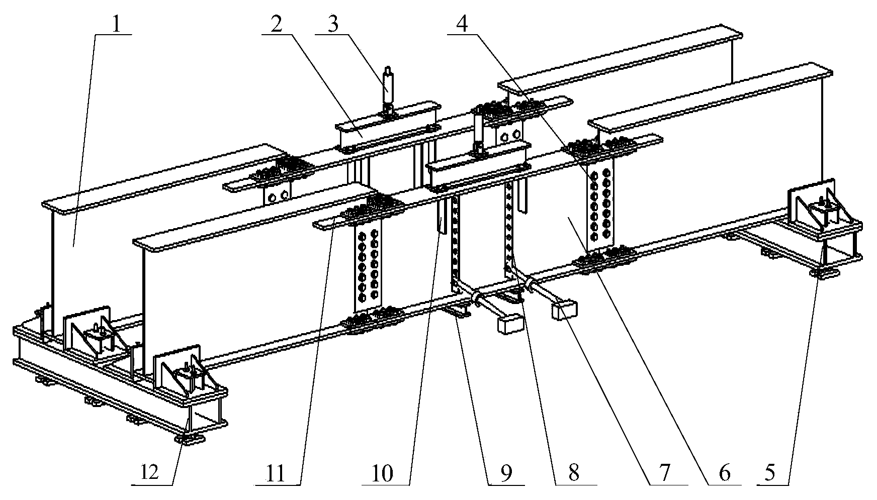
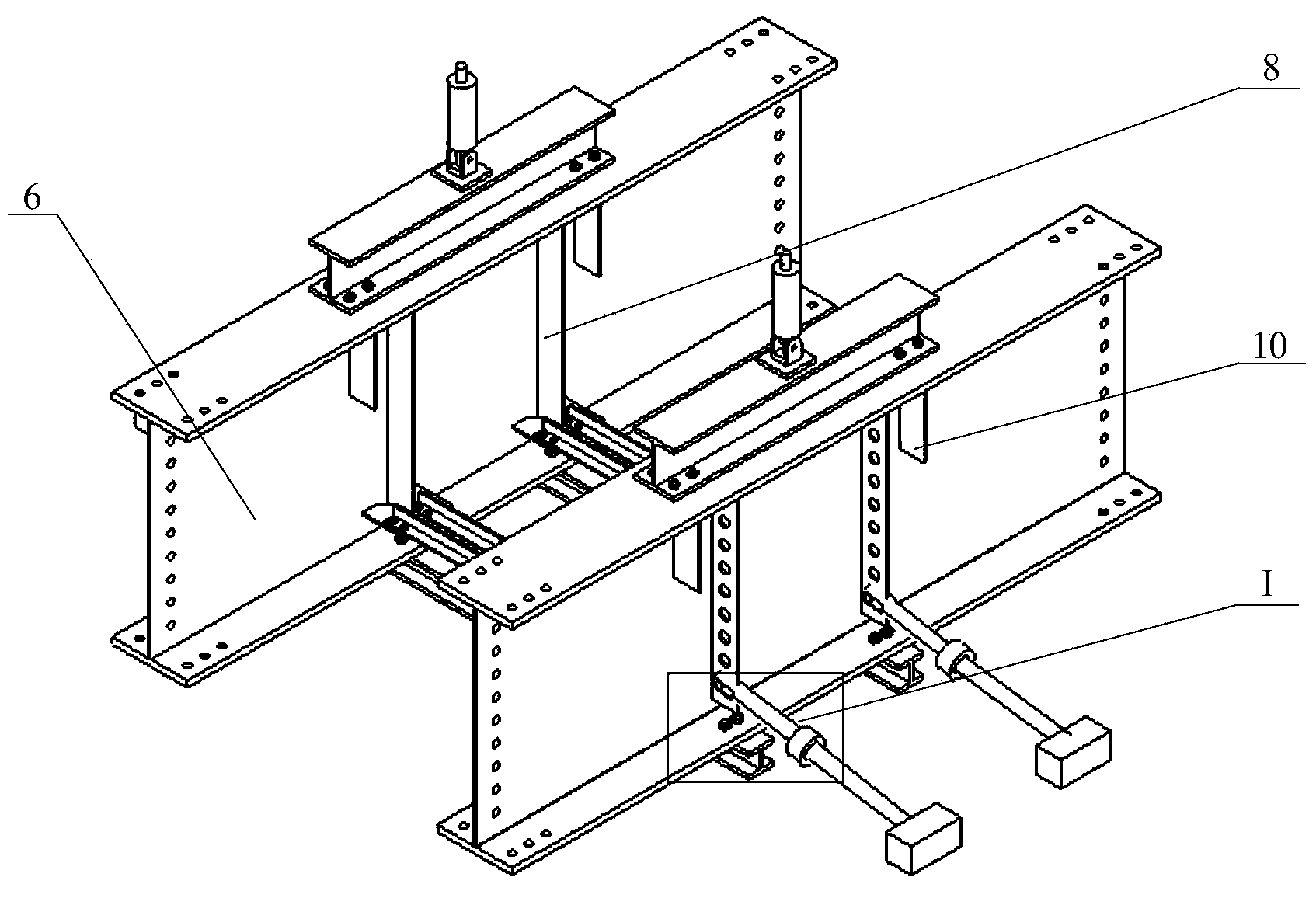
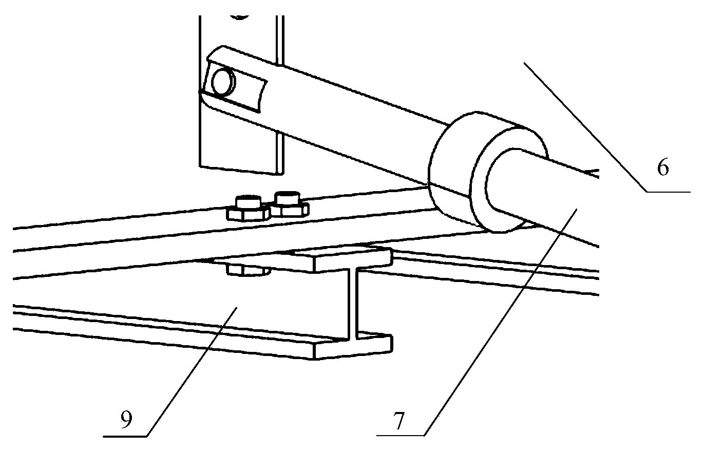
[0026] like Figure 1~4 and Figure 9 As shown, the full-scale fatigue test loading device for steel plate girder bridge deck deformation of the present invention consists of an auxiliary beam 1, a loading beam 2, a servo hydraulic actuator 3, a connecting plate 4, a rear auxiliary beam section support structure 5, and a diagonal brace 7 , vertical stiffener 8, connecting steel 9, loading point stiffener 10, horizontal stiffener 11, front auxiliary beam section support structure 12, steel backing plate 13, flat joint 14, and horizontal gusset plate 15.

[0027] The steel backing plate 13 is placed at the loading point position of the upper end of the test beam 6, and the steel backing plate 13 is processed with a bolt connection hole, the loading beam 2 is hoisted on the steel backing plate 13 and the test beam 6, the steel backing plate 13 and the loading The beam 2 is fixedly connected, and the mid-span roof of the loading beam 2 is fixedly connected to the servo hydraulic ...

Embodiment 2

[0036] like Figure 11-12 As shown, the horizontal gusset plate 15 of this embodiment is connected to the web of the test beam 6 by welding, the end of the horizontal gusset plate 15 is welded to the web of the test beam 6, and the U-shaped groove is processed in the middle to span the vertical stiffener 8 and leave a web gap with the vertical stiffener 8.

[0037] The bottom of the test beam 6 is connected with 5 connecting section steels 9 with bolts.

[0038] The upper flange plate of the front support anchor box 12-5 is the same size as the lower flange plate, both of which are rectangular steel plates with a width of 400mm, a thickness of 10mm and a length of 2000mm; the left web of the front support anchor box 12-5 and the The right webs have the same size, they are all rectangular steel plates with a width of 250 mm, a thickness of 8 mm, and a length of 2000 mm; the vertical arm of the front lateral restraint 12-1 is a rectangular steel plate with a width of 200 mm, a ...

Embodiment 3

[0043] The bottom of the test beam 6 is connected with 8 connecting section steels 9 with bolts.

[0044] The upper and lower flanges of the front support anchor box 12-5 have the same geometric shape and size, both are rectangular steel plates with a width of 600mm, a thickness of 50mm and a length of 3000mm; the left abdomen of the front support steel 12-3 The geometric shape and size of the plate and the right web are the same, they are both rectangular steel plates with a width of 400 mm, a thickness of 24 mm, and a length of 3000 mm; the vertical arm of the front lateral restraint 12-1 is 300 mm in width, 28 mm in thickness, and 600mm rectangular steel plate, the horizontal arm of the front lateral restraint 12-1 is a rectangular steel plate with a width of 500mm, a thickness of 28mm, and a length of 600mm.

[0045] The rear support anchor box 5-5 has the same structure and size as the front support anchor box 12-5, and the rear lateral restraint 5-1 has the same structur...


PUM

PropertyMeasurementUnit
widthaaaaaaaaaa
thicknessaaaaaaaaaa
lengthaaaaaaaaaa

Abstract

The invention relates to a steel plate beam bridge face outer deformation full size fatigue test loading device. A test beam is provided with a steel cushion plate, a loading beam and a servo hydraulic actuator. A test beam web is provided with vertical stiffening ribs, the adjusting ends of diagonal bars are arranged on the vertical stiffening ribs, and the supporting ends of the diagonal bars are arranged on anchoring blocks. The bottom of the test beam is provided with connecting structural steel, and the two ends of the test beam are provided with auxiliary beams. The joints of the auxiliary beams and the test beam are provided with horizontal stiffening ribs, connecting plates are arranged between the auxiliary beams and the test beam, the bottom of the front auxiliary beam and the bottom of the rear auxiliary beam are provided with a front auxiliary beam segment supporting structure and a rear auxiliary beam segment supporting structure respectively, and the front auxiliary beam and the rear auxiliary beam are fixed to troughs respectively. The test beam, the loading beam, the auxiliary beams and the connecting structures of the test beam, the loading beam and the auxiliary beams form a right beam segment. The left ends of the front auxiliary beam segment supporting structure, the rear auxiliary beam segment supporting structure and the connecting structural steel are provided with left beam segments which have the same structure and the opposite direction with the right beam segment, and the left beam segments are parallel to the right beam segment. Loading point stiffening ribs are arranged on the two sides of the vertical stiffening ribs of the test beam web, horizontal joint plates are arranged between the lower ends of the vertical stiffening ribs on the inner side and the test beam web, and a left beam segment horizontal joint plate is connected with a right beam segment horizontal joint plate in parallel.

Description

technical field [0001] The invention belongs to the technical field of bridge engineering, and in particular relates to a loading device for a full-scale fatigue test of steel plate girder bridge surface deformation. Background technique [0002] With the wide application of steel structure bridges, the fatigue problem of steel bridges has become increasingly prominent. Fatigue problems of steel bridges seriously affect the safety of bridges, and studies have shown that secondary stress and out-of-plane deformation at fatigue-sensitive details are the main causes of fatigue cracking. In the design of steel bridges, it is necessary to use horizontal connection systems and parallel connections to realize the horizontal connection between the steel girders. In order to avoid fatigue failure of the welding details between the vertical stiffener and the tension flange of the main beam, a web gap of tens of millimeters is usually left between the vertical stiffener and the tensio...

Claims


Application Information

Patent Timeline
Patent Type & Authority Applications(China)
IPC IPC(8): G01N3/02G01N3/12
Inventor 王春生王茜孙宇佳段兰魏孟春赵金伟
Owner CHANGAN UNIV
Why Eureka
Try Eureka