
Touch device and touch driving method

A touch device, touch panel technology, applied in the direction of instruments, computing, electrical digital data processing, etc., can solve the problems of high refresh rate, lower frame rate, LCD screen can not work, etc., achieve high refresh rate, reduce power consumption effect

Inactive Publication Date: 2017-02-15
HEFEI XINSHENG OPTOELECTRONICS TECH CO LTD +1
View PDF8 Cites 0 Cited by
  • Summary
  • Abstract
  • Description
  • Claims
  • Application Information

AI Technical Summary

Problems solved by technology

When t is small, the scanning of Tx and Rx will not be completed, so it is necessary to increase t appropriately. At present, the direct way to increase t is to increase the scanning time of one frame, but this means reducing the frame rate and will affect the screen display. effect, there are problems such as flickering and smearing
[0005] In summary, due to the time-sharing driving method used in the prior art in-cell touch technology LCD screen, the LCD screen cannot work at a higher refresh rate when not being touched.

Method used


Image

  • Touch device and touch driving method
  • Touch device and touch driving method
  • Touch device and touch driving method

Examples


Embodiment Construction

[0044]Embodiments of the present invention provide a touch device and a touch driving method, which are used to realize that the touch device works at a higher refresh rate when not being touched.

[0045] The touch device provided by the specific embodiments of the present invention and its specific working process will be described in detail below in conjunction with the accompanying drawings.

[0046] Such as Figure 4 As shown, a specific embodiment of the present invention provides a touch device, which includes a touch panel 40, a timing controller 41, a touch controller 42, a controller 43 and a sensor 44, wherein:

[0047] The sensor 44 is used to detect whether there is an object touching or approaching the touch panel 40, and when there is no object touching or approaching the touch panel 40, the first indication signal is output to the controller 43; or when approaching the touch panel 40, outputting a second indication signal to the controller 43;

[0048] The co...


PUM


Abstract

The invention discloses a touch device and a touch driving method, which are used to realize that the touch device works at a higher refresh rate when it is not touched. The touch device includes a touch panel, a timing controller, a touch controller, a controller and a sensor, wherein: the sensor is used to detect whether an object touches or approaches the touch panel; when no object touches or approaches the touch panel, Output the first indication signal to the controller; when an object touches or approaches the touch panel, output the second indication signal to the controller; the controller is used to receive the first indication signal, control the touch controller not to work, and control the timing controller Output the first scanning signal; and receive the second indication signal, control the timing controller to output the second scanning signal, and control the touch controller to start working; the scanning frequency of the first scanning signal is higher than the scanning frequency of the second scanning signal, and Both the first scan signal and the second scan signal are display scan signals of the touch panel.

Description

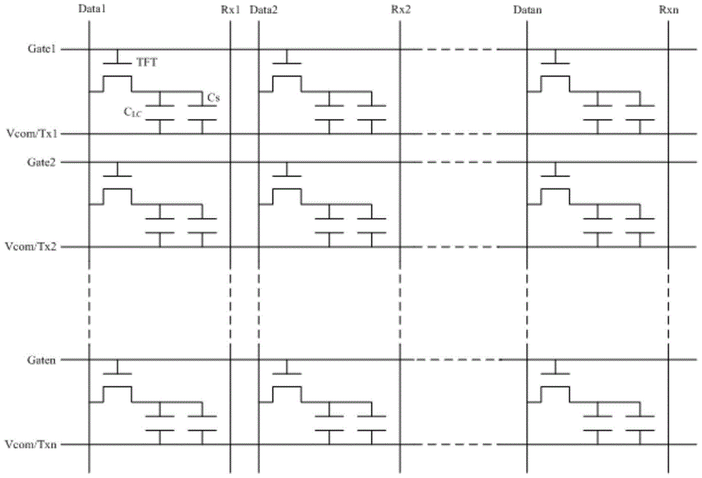
technical field [0001] The invention relates to the technical field of displays, in particular to a touch device and a touch driving method. Background technique [0002] Compared with the traditional external capacitive touch screen structure, the in-cell capacitive touch screen in the prior art can save a touch substrate and make the whole display module lighter and thinner. The schematic diagram of the structure of the liquid crystal display screen with in-cell touch technology is as follows: figure 1 As shown, the touch driving electrodes (Tx) and touch sensing electrodes (Rx) are fabricated on the glass substrate on the array substrate side of the liquid crystal display panel, wherein the Tx line is shared with the common electrode (Vcom) line, and the in-cell structure Various parasitic capacitances and coupling capacitances will be generated between the capacitive touch screen Tx and Rx and the thin film transistor (Thin Film Transistor, TFT) display device. Gate1, G...

Claims


Application Information

Patent Timeline
Patent Type & Authority Patents(China)
IPC IPC(8): G06F3/044G02F1/1333
CPCG06F3/0421G06F3/0436G06F3/0412G06F2203/04101G06F2203/04106G06F3/04166
Inventor 马韬张大宇
Owner HEFEI XINSHENG OPTOELECTRONICS TECH CO LTD
Learn More