
Circulating air arc-control device for small breaker

A small circuit breaker and circulating airflow technology, applied in the direction of circuit breaker components, etc., can solve the problems of back blowing, no current limiting function, no magnetic blowing and air blowing functions, etc., to prevent arc reignition, increase arc voltage, The effect of preventing arc running

Inactive Publication Date: 2014-09-24
BOER YIXING POWER SYST
View PDF7 Cites 5 Cited by
  • Summary
  • Abstract
  • Description
  • Claims
  • Application Information

AI Technical Summary

Problems solved by technology

[0002] The existing miniature circuit breaker arc extinguishing system is extremely poorly closed and cannot prevent the arc from running around; without the function of magnetic blowing and air blowing, the directionality of the magnetic field and air flow field cannot be guaranteed, and it is easy to cause back blowing and affect the effectiveness of the driving force of the arc ; It cannot guarantee that the arc is effectively pushed into the grid arc extinguishing chamber device and the arc is effectively extinguished in the grid arc extinguishing chamber device; and the current limiting performance of the existing grid arc extinguishing system is extremely poor or has no current limiting function at all

Method used


Image

  • Circulating air arc-control device for small breaker
  • Circulating air arc-control device for small breaker
  • Circulating air arc-control device for small breaker

Examples


Embodiment Construction

[0019] The present invention will be further described below in conjunction with the accompanying drawings and embodiments.

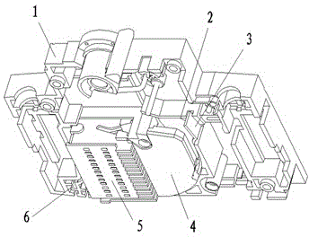
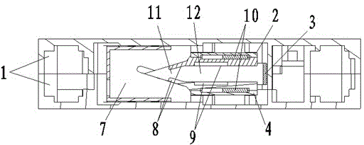
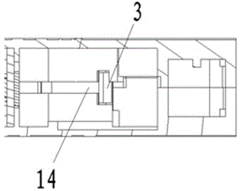
[0020] to combine figure 1 , figure 2 , image 3 : The circular air flow arc extinguishing device used for small circuit breakers of the present invention includes a housing 1, and a grid arc extinguishing chamber 5, an upper partition 4, a lower partition 2, an air outlet 6 and an arc strike plate 3 are installed in the housing , in the contact area and the head area of ​​the arc striker, the upper partition 4 and the lower partition 2 make the arc extinguishing system form a semi-closed form up and down, and a contact movement groove 14 is reserved in the partition to ensure that the contact movement cannot be interfered , the upper partition 4 and the lower partition 2 separate the arc extinguishing chamber 5 from the circuit breaker mechanism, so that a certain gas pressure can be stored, and the pressure rise caused by the arc energy in the arc ...


PUM


Abstract

The invention discloses a circulating air arc-control device for a small breaker. The circulating air arc-control device comprises a shell, a grating sheet arc extinguish chamber, an upper baffle, a lower baffle, an air outlet and a run-on plate, wherein the grating sheet arc extinguish chamber, the upper baffle, the lower baffle, the air outlet and the run-on plate are arranged in the shell, one sides of the upper baffle and the lower baffle are buckled with the grating sheet arc extinguish chamber, and arcing rings are arranged in the upper baffle and the lower baffle; a necking is formed in the tail end of each arcing ring and is matched with an electric arc of the grating sheet arc extinguish chamber, and the air outlet is arranged at the bottom of the grating sheet arc extinguish chamber; after the electric arc is generated and leaves away from a contact, the electric arc enters the grating sheet arc extinguish chamber along the run-on plate and the necking sequentially, and gas is discharged by the air outlet after the arc extinction. The circulating air arc-control device provided by the invention is good in sealing capability, is capable of preventing the electric arc from stampeding and guaranteeing the directivity of magnetic blow-out and air-blowing, namely, the reserve blowing function of the electric arc can be prevented, the phenomenon that the electric arc is effectively driven to enter the grating sheet arc extinguish chamber and is quenched, the electric arc is reburnt and punched on the back can be prevented, and the electric arc voltage can be quickly improved, therefore, the good limit effect can be achieved.

Description

technical field [0001] The invention relates to the field of low-voltage electrical industry, in particular to an arc extinguishing device with good sealing performance for a small circuit breaker, in particular to a circular airflow arc extinguishing device for a small circuit breaker. Background technique [0002] The existing miniature circuit breaker arc extinguishing system is extremely poorly closed and cannot prevent the arc from running around; without the function of magnetic blowing and air blowing, the directionality of the magnetic field and air flow field cannot be guaranteed, and it is easy to cause back blowing and affect the effectiveness of the driving force of the arc ; Can not guarantee that the arc is effectively pushed into the grid arc extinguishing chamber device and the arc is effectively extinguished in the grid arc extinguishing chamber device; and the current limiting performance of the existing grid arc extinguishing system is extremely poor or h...

Claims


Application Information

Patent Timeline
IPC IPC(8): H01H73/18
Inventor 王登权
Owner BOER YIXING POWER SYST
Learn More