Solar cell module and method of fabricating the same

A solar cell and electrical connection technology, applied in the direction of photovoltaic modules, photovoltaic module support structures, circuits, etc., can solve problems such as reducing reliability, and achieve the effect of reducing failure rate and improving reliability.

Inactive Publication Date: 2014-09-24
LG INNOTEK CO LTD
View PDF8 Cites 3 Cited by
  • Summary
  • Abstract
  • Description
  • Claims
  • Application Information

AI Technical Summary

Problems solved by technology

In general, when a bus line formed on the upper surface of a solar cell panel is connected to a junction box fo

Method used


Image

  • Solar cell module and method of fabricating the same
  • Solar cell module and method of fabricating the same
  • Solar cell module and method of fabricating the same

Examples


Embodiment Construction

[0025] In the description of the embodiments, it will be understood that when a panel, strip, frame, substrate, hole or film is referred to as being in another panel, another strip, another frame, another substrate, another hole or another When a film is on or off, it can be directly or indirectly on another panel, another strip, another frame, another substrate, another hole or another film, or there can also be one or more intervening layers . Such positions of layers have been described with reference to the drawings. The size of elements shown in the drawings may be exaggerated for illustrative purposes and may not fully reflect actual sizes.

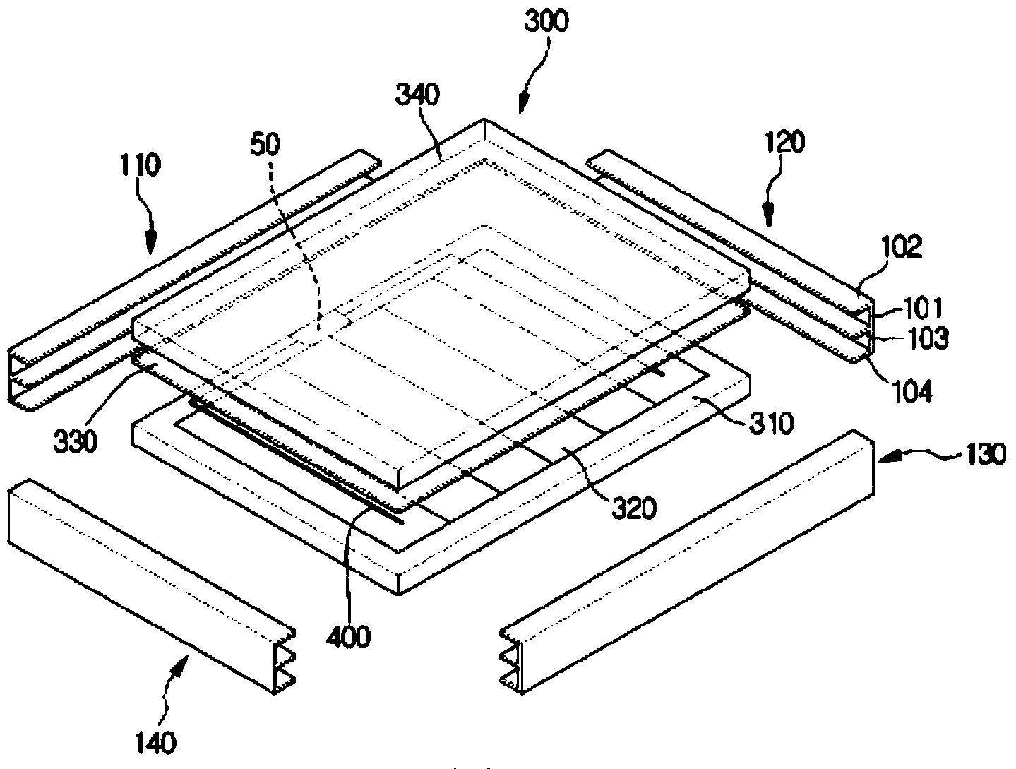
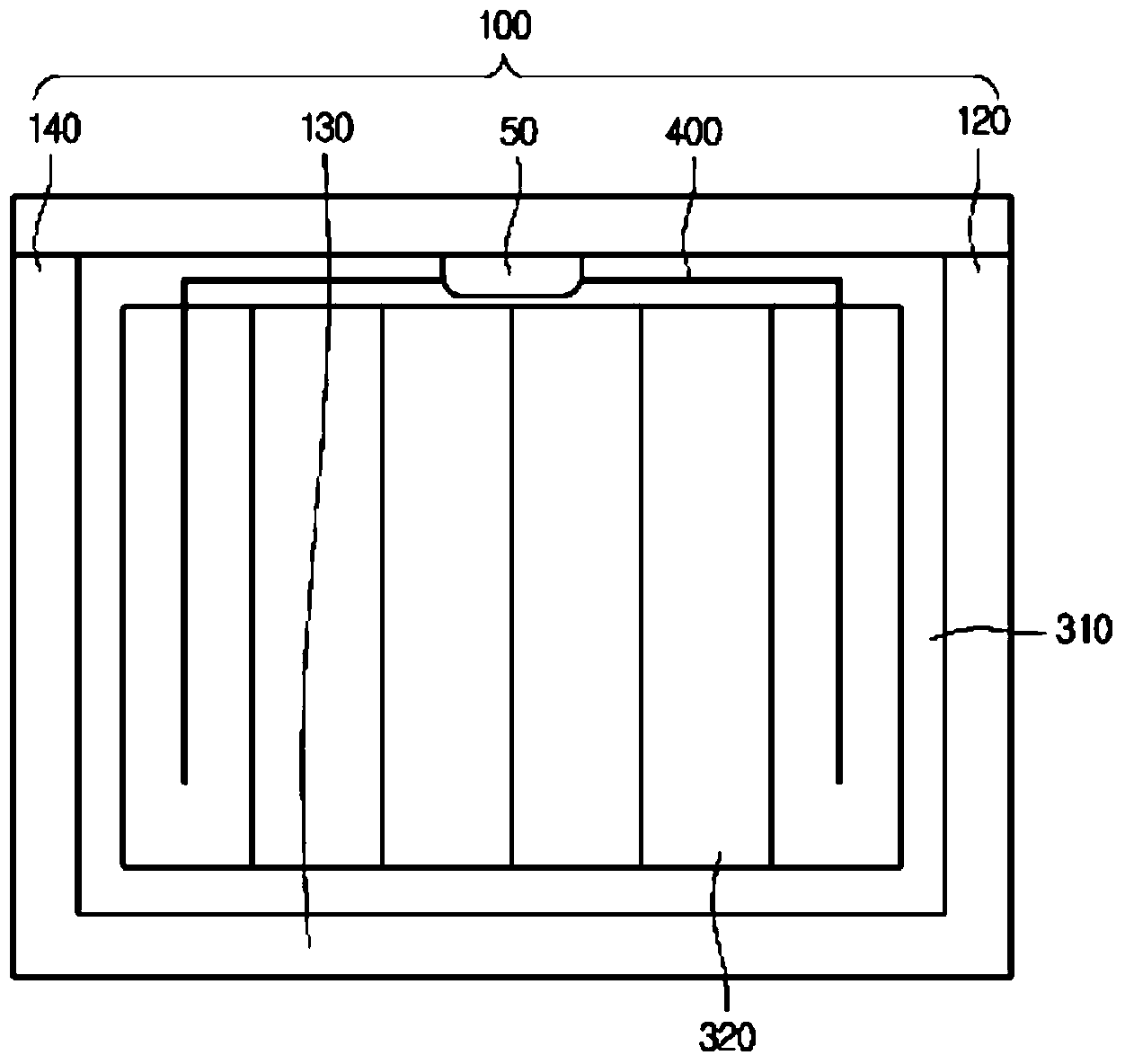
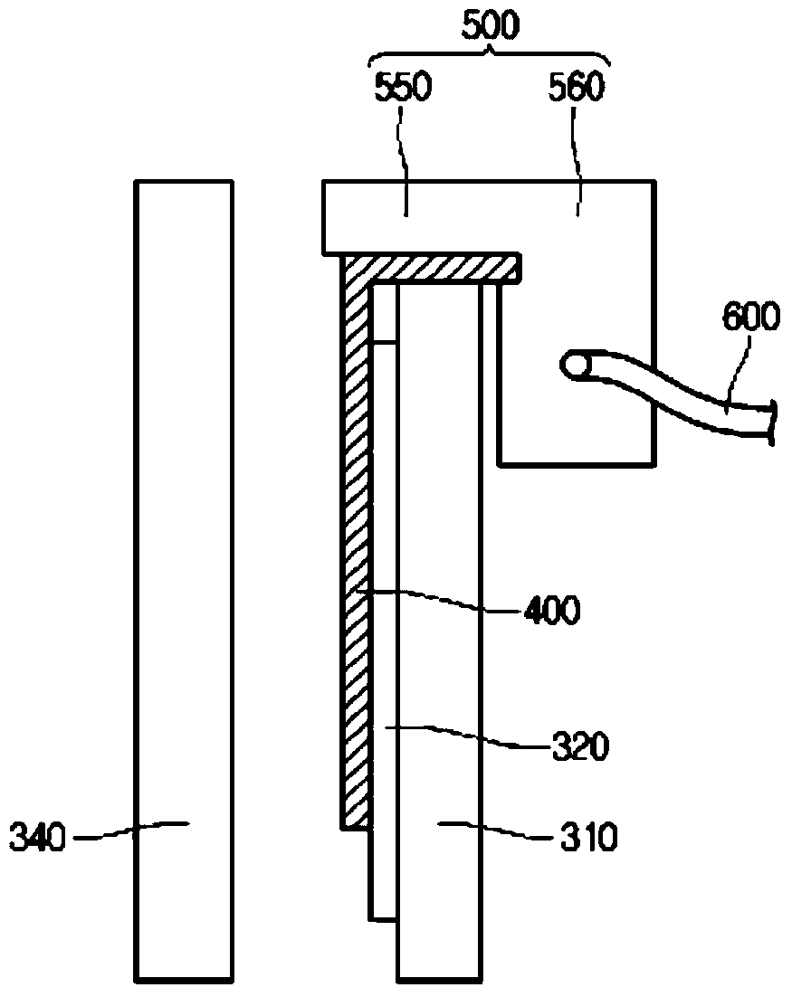
[0026] figure 1 is a perspective view showing the solar cell module according to the first embodiment. figure 2 is shown figure 1 Top view of the solar cell module. image 3 is shown figure 1 Cutaway view of a solar cell module. Figure 4 is shown figure 1 Perspective view of the junction box.

[0027] The solar cell modul...


PUM


Abstract

A solar cell module according to the embodiment includes a support substrate having a single hole at a peripheral region of the support substrate; solar cells at an upper portion of the support substrate; a bus bar electrically connected to the solar cells; and a junction box connected to the bus bar, wherein the junction box includes an insertion part partially inserted in the single hole.

Description

technical field [0001] Embodiments relate to a solar cell module and a method of manufacturing the same, and more particularly, to a solar cell module capable of improving reliability and productivity and a method of manufacturing the same. Background technique [0002] Recently, there has been increasing interest in alternative energy sources due to the expectation that energy sources such as oil or coal will be scarce. In this regard, solar cells, which convert solar energy into electricity, are in focus. [0003] A solar cell (or photovoltaic cell) is the core element of solar power generation that directly converts sunlight into electricity. [0004] For example, if sunlight with energy greater than the bandgap energy of a semiconductor is incident on a solar cell having a PN junction structure, electron-hole pairs are generated. Due to the electric field formed in the PN junction portion, electrons and holes gather to the N layer and the P layer, respectively, so that...

Claims


Application Information

Patent Timeline
IPC IPC(8): H02S20/00H02S40/34
CPCH01L31/0485H02S40/34H02S20/00Y02E10/50H01L31/0422H02S20/26H02S30/10Y02B10/10H01L31/0201
Inventor 朴智鸿
Owner LG INNOTEK CO LTD
Why Eureka
Try Eureka