Motor shaft quenching equipment

A technology for quenching equipment and motor shafts, applied in the direction of quenching devices, heat treatment equipment, furnaces, etc., can solve the problems of low production efficiency, pollution, and large difference in quenching hardness, etc., to improve production efficiency, reduce labor intensity, and automation high effect

Active Publication Date: 2014-10-01
NINGBO COLET ELECTRICAL APPLIANCE
View PDF6 Cites 10 Cited by
  • Summary
  • Abstract
  • Description
  • Claims
  • Application Information

AI Technical Summary

Problems solved by technology

In the current heat treatment process, most of them use ordinary medium and high frequency induction heating machine tools. Since there is no relevant semi-automatic or fully automatic quenching equipment on the market, this process can only be carried out manually, and manual operation requires Skilled operators also have the following disadvantages:
[0003] A. The production efficiency is low, 1 person / 2000PCS / 8H, which cannot meet the production needs of large-scale and large-scale motor shafts;
[0004] B. The working environment is harsh and filthy, which affects the physical and mental health of employees;
[0005] C. Manual operation will be affected by factors such as time and environment, resulting in a large difference in quenching hardness, which is not conducive to the stability of product quality

Method used


Image

  • Motor shaft quenching equipment
  • Motor shaft quenching equipment
  • Motor shaft quenching equipment

Examples


Embodiment Construction

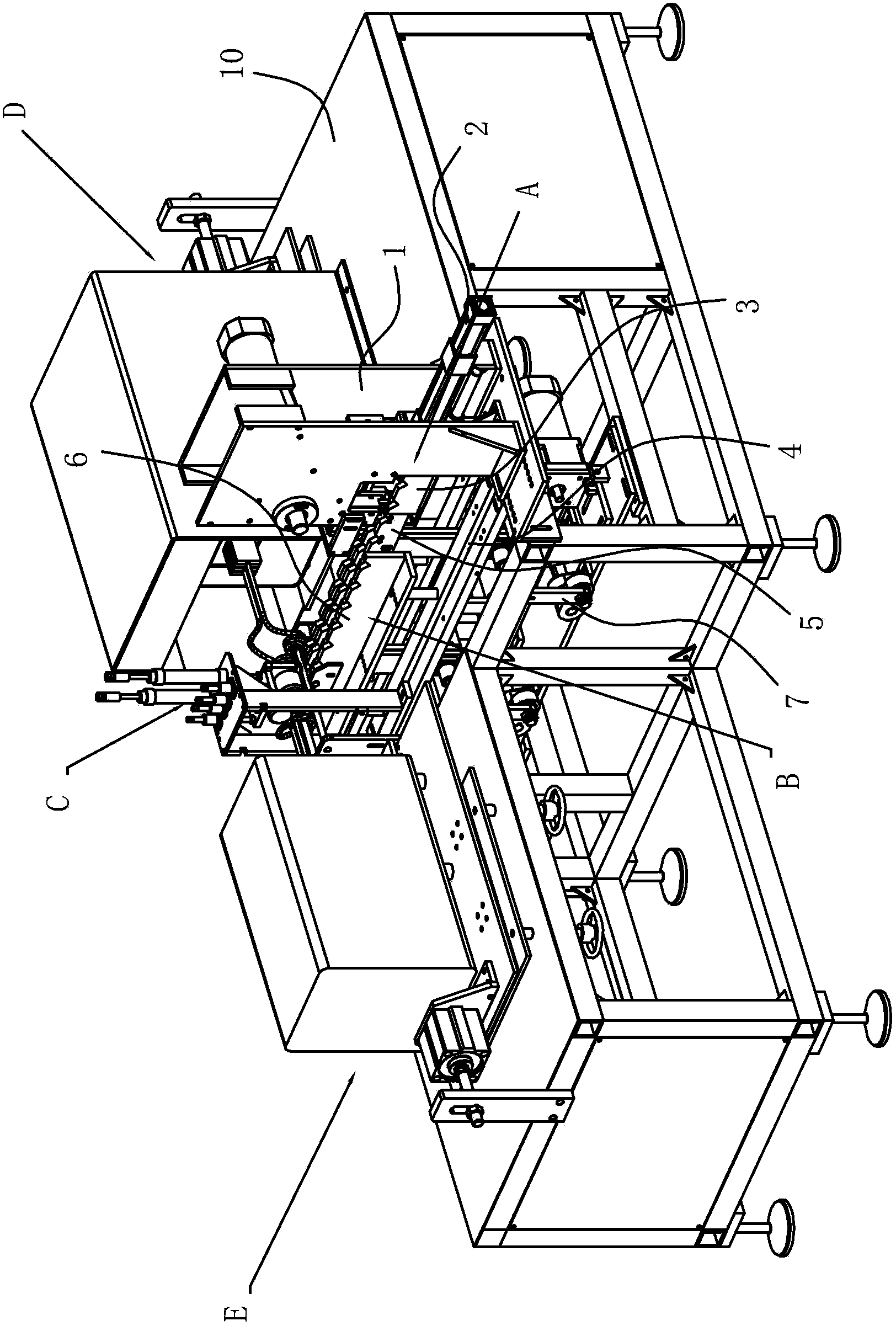
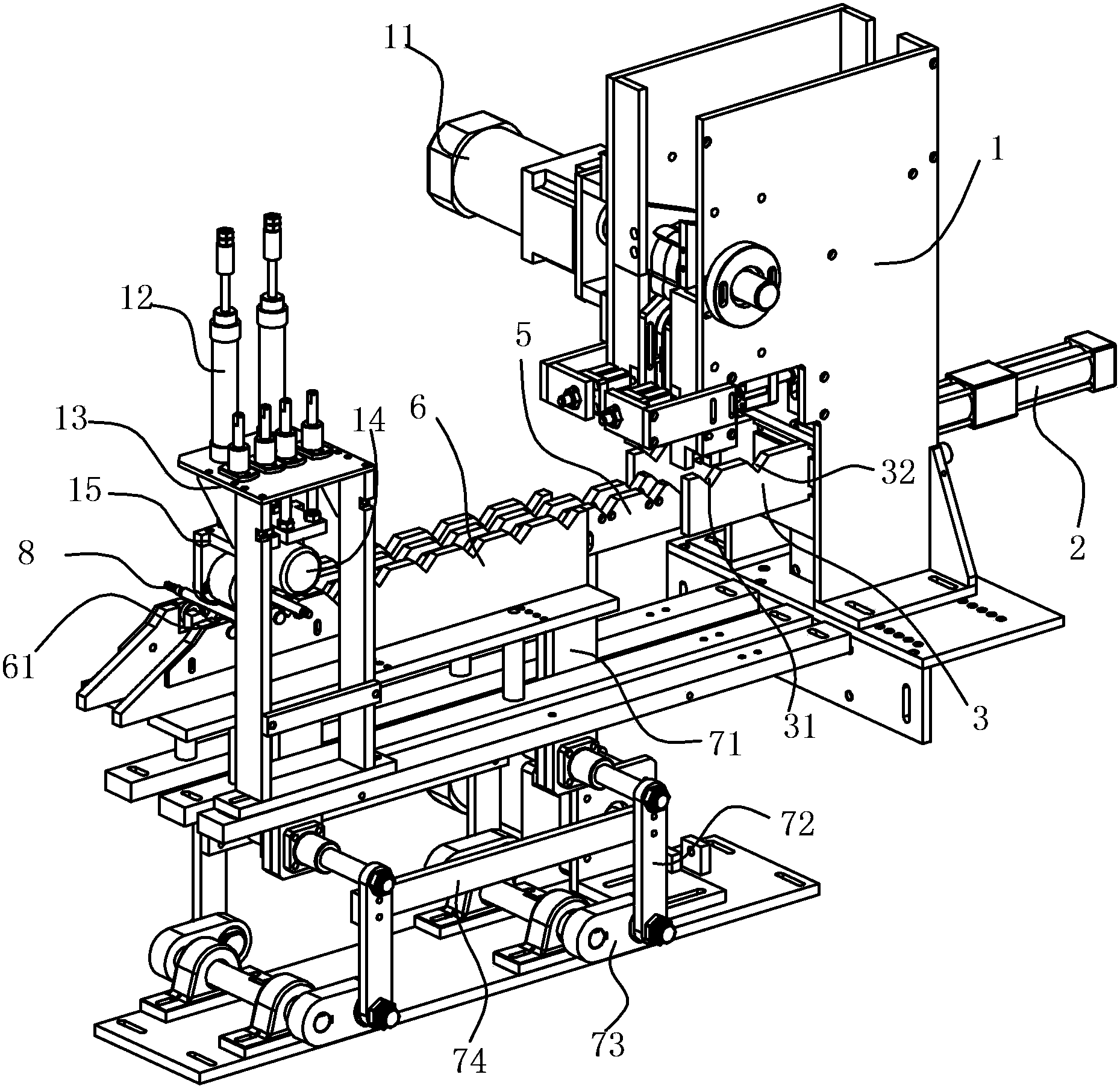
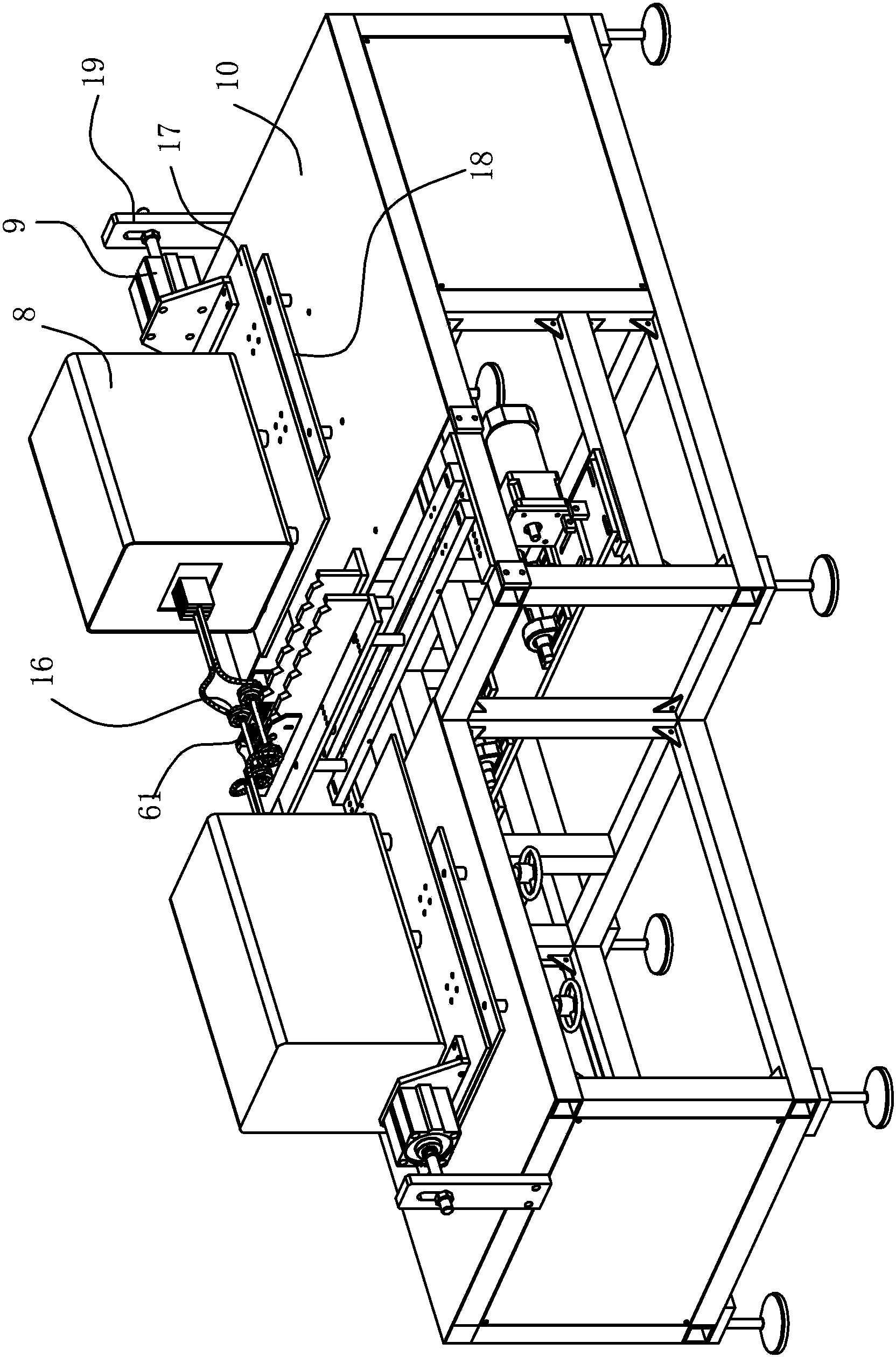
[0028] The present invention will be further described in detail below in conjunction with the accompanying drawings and embodiments.

[0029] As shown in the figure, a fully automatic serial excitation motor shaft quenching equipment is mainly composed of automatic discharge and feeding mechanism A, automatic feeding and discharging mechanism B, pressing and rotating mechanism C, quenching sending and retracting mechanism, cooling mechanism and program control Composed of the system, the automatic discharge feeding mechanism A and the automatic feeding and discharging mechanism B are sequentially set on a strip-shaped machine base 4 from the back to the front;

[0030] The automatic discharge and feeding mechanism A includes a hopper 1, a linear feeding plate 3, a feeding motor 11 for driving the feeding opening, and a feeding cylinder 2. The hopper 1 is erected at the rear of the machine base 4, and the feeding motor 11 is installed on the side of the hopper 1. There are two...


PUM


Abstract

The invention discloses motor shaft quenching equipment which is characterized by mainly comprising an automatic discharging and charging mechanism, an automatic feeding and discharging mechanism, a pressing and rotating mechanism and a quenching delivery and recovery mechanism, wherein the automatic discharging and charging mechanism comprises a hopper, a linear feeding plate, a feeding motor and a feeding cylinder; the linear feeding plate is arranged under the hopper; the feeding cylinder is connected with the linear feeding plate; the automatic feeding and discharging mechanism consists of a fixed conveying plate, a movable conveying plate and a crank connecting rod system; a quenching tank is arranged at the forefront end of the fixed conveying plate; the movable conveying plate is driven by the crank connecting rod system to be arranged between the linear feeding plate and the fixed conveying plate in an eccentric leapfrog mode, and workpieces are conveyed from the linear feeding plate to the quenching tank of the fixed conveying plate. A series excited machine shaft can be automatically quenched, the labor intensity is reduced, and the production efficiency is improved. Moreover, the quality is stable and reliable, the product yield is improved, and the motor shaft quenching equipment can be applied to large-scale mass production of series excited machine shafts.

Description

technical field [0001] The invention belongs to the technical field of processing machinery and equipment, and relates to a quenching machine, in particular to an automatic series excitation machine that automatically sends the shaft of a series excitation motor to a fixed position, and the quenching machine heats and cools the parts that require heat treatment at both ends. Motor shaft quenching equipment Background technique [0002] During the use of the series motor shaft, the main cause of failure is the wear of the surface and both ends. In the current heat treatment process, most of the ordinary medium and high frequency induction heating machine tools are used. Since there is no relevant semi-automatic or fully automatic quenching equipment on the market, this process can only be carried out manually, and manual operation requires Skilled operators also have the following disadvantages: [0003] A. The production efficiency is low, 1 person / 2000PCS / 8H, which cannot...

Claims


Application Information

Patent Timeline
Patent Type & Authority Applications(China)
IPC IPC(8): C21D9/28C21D1/63
Inventor 沈高明
Owner NINGBO COLET ELECTRICAL APPLIANCE
Why Eureka
Try Eureka