
Fluid control valve

A fluid control valve, ball technology, applied in the direction of diaphragm valve, balance valve, valve device, etc., can solve the problems such as the increase of the offset of the actuator and the decrease of the stroke.

Active Publication Date: 2014-10-01
HORIBA STEC CO LTD
View PDF7 Cites 11 Cited by
  • Summary
  • Abstract
  • Description
  • Claims
  • Application Information

AI Technical Summary

Problems solved by technology

However, if the area of ​​the thin film portion is increased, the area that receives the pressure applied by the fluid on the protruding side of the pin in the direction perpendicular to the thin film portion, that is, the pressure in the direction opposite to the direction of movement of the pin increases, and the pressure applied from the actuator increases. The amount of force being offset is also substantially increased
Therefore, simply increasing the area of ​​the thin film may result in a decrease in the stroke amount.

Method used


Image

  • Fluid control valve
  • Fluid control valve
  • Fluid control valve

Examples


no. 1 approach

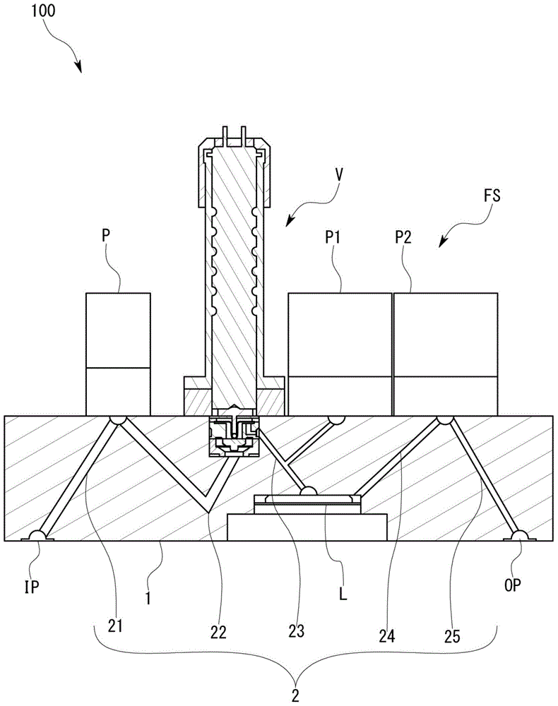
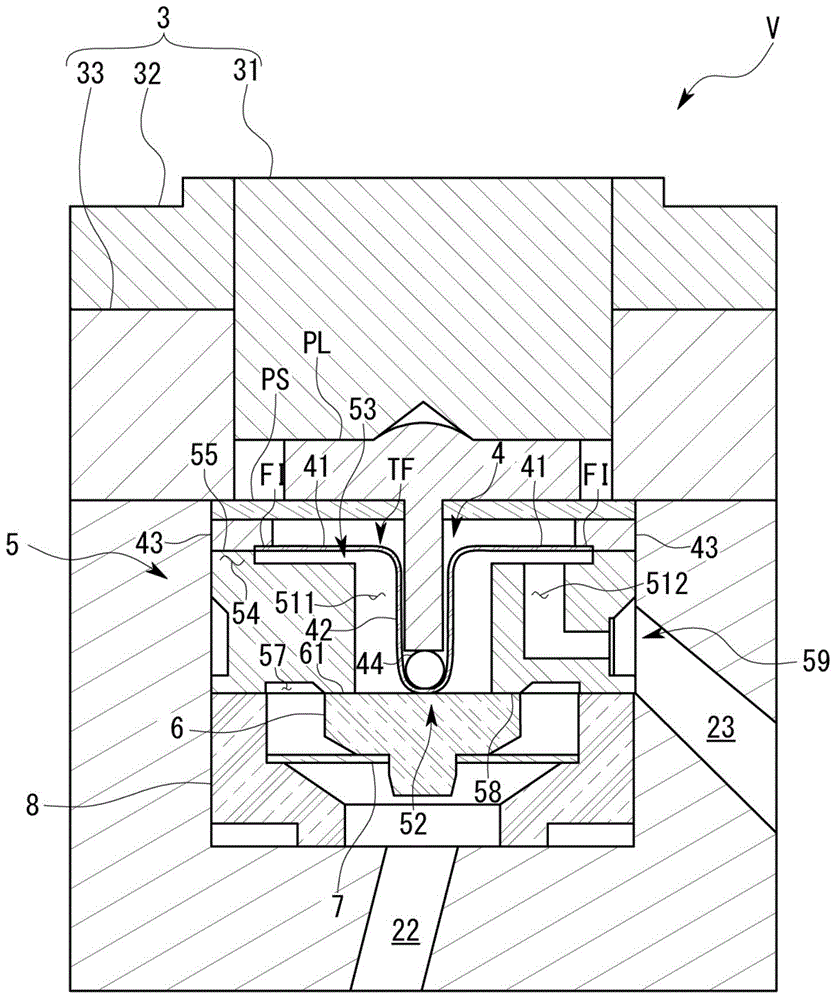
[0047] refer to Figures 1 to 6 The fluid control valve V and the mass flow controller 100 according to the first embodiment of the present invention will be described.

[0048] The mass flow controller 100 of the first embodiment is used in semiconductor manufacturing equipment such as figure 1 As shown, it includes: a main body 1, in which a flow channel 2 is formed to allow the fluid to be measured to flow; a primary pressure sensor P is used to measure the moment when the fluid flowing through the flow channel 2 flows into the main body 1 or enters the main body 1 before the pressure on the upstream side; the fluid control valve V is used to control the flow of the fluid flowing through the flow channel 2; the flow sensor FS is used to measure the flow of the fluid flowing through the flow channel 2; and the control part (not shown shown), feedback control the opening of the fluid control valve V to reduce the deviation between the target flow value and the measured flow ...

no. 2 approach

[0075] Then refer to Figure 8 and Figure 9 A second embodiment will be described. In addition, the same code|symbol is attached|subjected to the member corresponding to 1st Embodiment.

[0076] The fluid control valve V of the second embodiment differs from the first embodiment in the retaining structure of the ball 44 in the diaphragm structure 4 that transmits the force from the actuator 3 .

[0077] More specifically, as Figure 8 and Figure 9 As shown, the diaphragm structure 4 of the second embodiment also has an internal fitting member 45 that is tightly fitted to the inner peripheral surface of the protruding portion 42 and holds the protruding portion 42 . Sphere44.

[0078] The inner fitting member 45 has a substantially hollow cylindrical shape whose thickness increases from the upper side to the lower side, and the diameter of the outer peripheral surface is substantially the same as the inner diameter of the protruding portion 42 . A ball 44 that contacts ...


PUM


Abstract

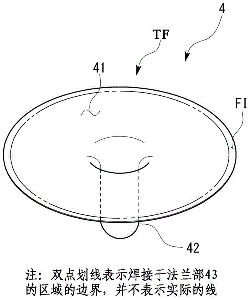
In order to make it possible to increase a diameter and output thereof, a diaphragm structure is provided that has low repulsiveness, can be largely deformed to increase a stroke even without being applied with a large force from an actuator, and is unlikely to give rise to a defect or fault even when formed thin, and a fluid control valve is provided with the diaphragm structure and the actuator that presses the diaphragm structure, wherein the diaphragm structure is provided with: a protruding part that is formed in a tubular shape and pressed by the actuator; a brim part that spreads from a base end of the protruding part outward with respect to the protruding part; and a support part that is formed on an outer circumference of the brim part and attached to another member, and the brim part is formed in a film shape.

Description

technical field [0001] The present invention relates to a fluid control valve used, for example, in a mass flow controller or the like that controls the flow rate of gas. Background technique [0002] The fluid control valve is interposed between the upstream side channel and the downstream side channel, and is used to control the flow rate and pressure of the fluid flowing therein, or to close it so that the fluid does not flow between the respective flow channels. For example, a normally closed fluid control valve is configured in such a way that it has a diaphragm structure that separates the flow path from the outside in the fluid control valve, and the actuator disposed on the outside side drives the actuator disposed on the flow path side through the diaphragm structure. The position of the valve body member among the valve seat member and the valve body member is changed to control the flow rate and pressure of the fluid. [0003] More specifically, the diaphragm str...

Claims


Application Information

Patent Timeline
Patent Type & Authority Applications(China)
IPC IPC(8): F16K17/20F16K31/04F16K37/00
CPCF16K15/144F16K7/12F16K31/007F16K37/0091F16K41/10
Inventor 安田忠弘林繁之河南宣之
Owner HORIBA STEC CO LTD
Learn More