
Device for improving fullness of combustible gas in shock wave generation tank

A technology for generating tank and fullness, which is applied in the field of boiler soot blowing, which can solve the problems of insufficient deflagration, insufficient mixing of gas and air, etc., and achieve the effects of increasing gas utilization rate, improving soot blowing effect, and ensuring correctness

Active Publication Date: 2014-10-01
BEIJING GUANGHUA TEXTILE GRP +1
View PDF7 Cites 5 Cited by
  • Summary
  • Abstract
  • Description
  • Claims
  • Application Information

AI Technical Summary

Problems solved by technology

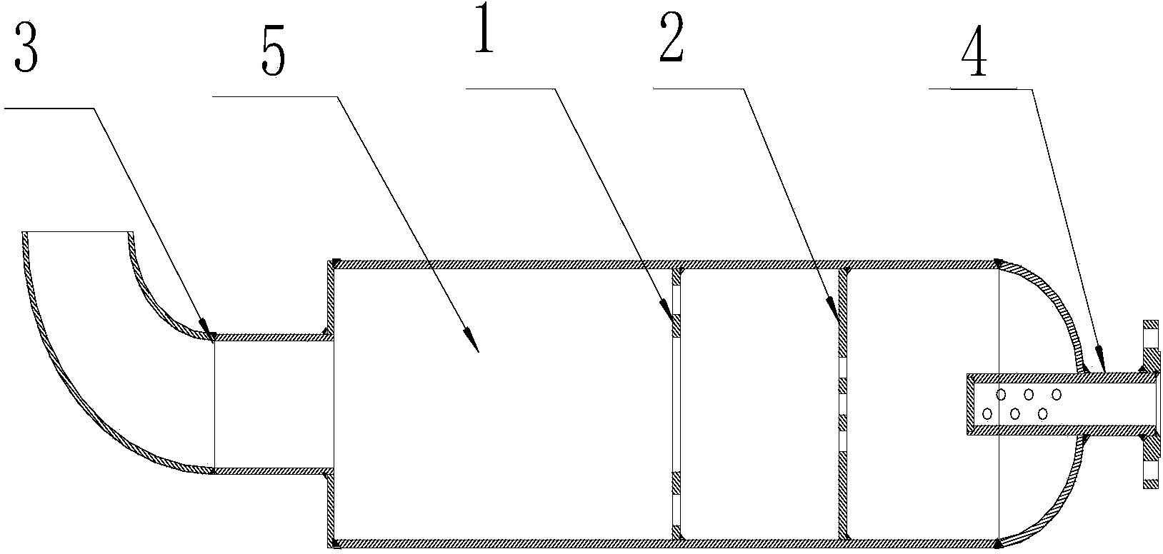
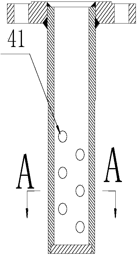
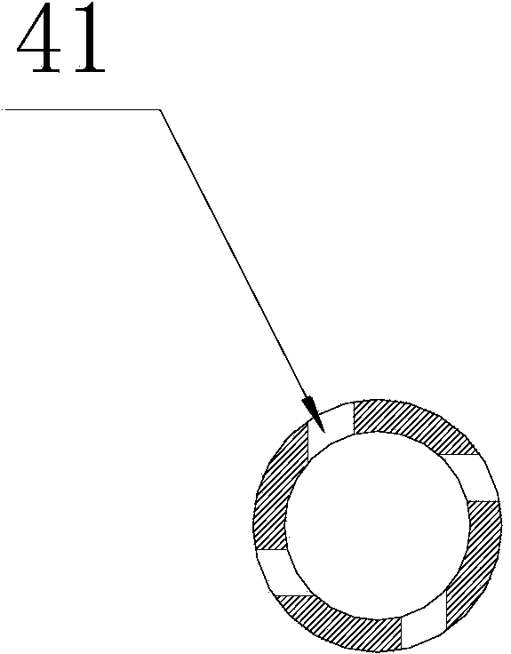
[0004] In order to solve the problem of insufficient deflagration caused by insufficient mixing of gas and air in the shock wave generating tank, the present invention provides a device for increasing the fullness of combustible gas in the shock wave generating tank, including an air inlet port, a sealing head, a first partition plate, a second partition, a generator tank and a spout; the air inlet port is fixedly connected to one end of the generator tank through the head, and the other end of the generator tank is fixed to the spout connection; the second baffle and the first baffle are sequentially arranged in the generator tank adjacent to the air inlet port according to the air intake direction, and the second baffle and the first baffle are arranged in parallel at a preset interval ; The inlet port is evenly provided with a plurality of inclined holes; the first partition is provided with a central through hole and inclined holes uniformly distributed along the circumference around the central through hole; the second partition It is provided with a central through hole and oblique holes and elongated through holes uniformly distributed along the circumference around the central through hole

Method used


Image

  • Device for improving fullness of combustible gas in shock wave generation tank
  • Device for improving fullness of combustible gas in shock wave generation tank
  • Device for improving fullness of combustible gas in shock wave generation tank

Examples


Embodiment Construction

[0019] The technical solutions of the present invention will be further described below with reference to the accompanying drawings and embodiments.

[0020] see Figure 1 to Figure 7 , the embodiment of the present invention provides a device for improving the fullness of combustible gas in a shock wave generating tank, including an air inlet port 4, a head, a first baffle 1, a second baffle 2, a generator tank 5 and a spout 3. Among them, the air inlet 4 is welded with one end of the generator tank body 5 through the head, and the other end of the generator tank body 5 is welded with the nozzle 3; In the generator tank 5 adjacent to the end of the air inlet port 4, and the second partition plate 2 and the first partition plate 1 are arranged in parallel at preset intervals; The plate 1 is provided with a central through hole 11 and oblique holes 12 evenly distributed along the circumference around the central through hole 11; the second partition plate 2 is provided with a...


PUM


Abstract

The invention discloses a device for improving fullness of combustible gas in a shock wave generation tank and belongs to the technical field of boiler soot blowing. The device comprises an air inlet connecting port, a seal head, a first partition plate, a second partition plate, a generator tank body and a nozzle. The air inlet connecting port is fixedly connected with one end of the generator tank body, the other end of the generator tank body is fixedly connected with the nozzle, and the second partition plate and the first partition plate are sequentially arranged in the generator tank body close to the air inlet connecting port end according to the air inlet direction and are parallelly arranged. The air inlet connecting port is provided with a plurality of inclined holes, the first partition plate is provided with a center through hole and inclined holes evenly distributed around the center through hole along the circumference, and the second partition plate is provided with a center through hole, inclined holes evenly distributed around the center through hole along the circumference and strip-shaped through holes. According to the device, mixed gas can evenly rapid fill the generator tank body, energy of gas shock waves is maximized, and the gas utilization rate of a shock wave generation system and the soot blowing effect are improved.

Description

technical field [0001] The invention relates to the technical field of boiler soot blowing, in particular to a device for improving the fullness of combustible gas in a shock wave generating tank. Background technique [0002] Soot blower is an indispensable and important auxiliary equipment for various waste heat boilers and power station boilers. It plays a vital role in improving the heat exchange efficiency of each heating surface of the boiler, that is, improving the output of the boiler. There are many types of sootblowers, such as: steam sootblowers, sonic sootblowers, air shock sootblowers and gas shock sootblowers. Different types of sootblowers have different characteristics and scope of application, but gas shock wave sootblowers have many advantages that other sootblowers do not have, which are mainly reflected in: large soot blowing energy, stable soot blowing operation, and maintenance. Small volume, low operating cost and wide application range. Therefore, t...

Claims


Application Information

Patent Timeline
Patent Type & Authority Applications(China)
IPC IPC(8): F23J1/00F23J3/00
Inventor 廖志超张博张明红刘康钟声赵勇
Owner BEIJING GUANGHUA TEXTILE GRP
Learn More