A soot blowing method and device for flushing the secondary air chamber of a boiler

A secondary air chamber and boiler technology, which is applied in the direction of combustion method, combustion product treatment, solid residue removal, etc., can solve the problems of secondary air chamber flow area change, dust accumulation, low construction cost, etc., and achieve shortening The effect of construction period and construction difficulty, reduction of renovation cost, and short construction period

Active Publication Date: 2016-08-31
HUADIAN ELECTRIC POWER SCI INST CO LTD
View PDF9 Cites 0 Cited by
  • Summary
  • Abstract
  • Description
  • Claims
  • Application Information

AI Technical Summary

Problems solved by technology

The main reason is: the hot flue gas and the cold secondary air exchange heat and cold in the air preheater, and when the cold secondary air performs heat exchange in the air preheater, the soot in the flue gas is entrained to the flushing boiler In the secondary air chamber, when the unit load is low and the secondary air volume is small, it is easy to cause ash accumulation in the secondary air chamber of the hedging boiler, and with the increase of the ash accumulation, the flow area of ​​the secondary air chamber of the hedging boiler will be damaged. changes, affecting the distribution of the flow field in the furnace, making the boiler unable to operate in the design state, which may cause coking in the furnace, high temperature corrosion and other problems
In severe cases, it will indirectly lead to serious accidents such as boiler water wall tube burst and unit shutdown
[0003] In the prior art, the dust removal work mainly waits for the unit to shut down normally or abnormally, and manually enters the secondary air chamber of the hedge boiler to clean the dust. The disadvantage is that the dust removal work cannot be completed while the unit is running. After the dust is removed, it can only last for a short time. With the operation of the unit, the dust accumulation becomes more serious, so that the secondary air chamber of the hedge boiler is always in a state of high dust. In essence, the dust removal fails and there is no dust removal effect.
In addition, in the prior art, by arranging the ash hopper at the bottom of the air chamber, the dust is removed through the ash hopper, the cost of the transformation is huge, the transformation period is long, and sufficient space is required for the installation.
[0004] There are also some soot blowing devices now, such as February 08, 2012, the Chinese patent with the publication number CN202137065U, which discloses a soot blowing device of a multi-pipe cyclone dust collector, which includes a dust removal box and The cyclone dust collector is installed in the dust removal box. There is an air main pipe with multiple shunt pipes outside the dust removal box. Connected with the above conveying pipe, there are multiple soot blowing ports on the soot blowing pipe, and the soot blowing ports are located above the cyclone dust collector, but this soot blowing device is not suitable for soot blowing in the secondary air chamber of the flushing boiler.
Another example is that the publication date is December 10, 2003, and the publication number is CN2591426. In the Chinese patent, a fully automatic computer soot blower is disclosed. , computer switch, electric device, air supply pipe, high-speed soot blowing nozzle, etc. The high-pressure air generated by the high-pressure fan is released into the confluence chamber through the automatic switch valve, rotated by the electric device, and supplied to the high-speed soot blowing nozzle through the air supply pipe , to jet the wind to the soot deposit at high speed, but the structure of the automatic computer soot blower is complicated, and it is not suitable for soot blowing in the secondary air chamber of the flushing boiler
[0005] To sum up, there is currently no soot blowing method and device for flushing the secondary air chamber of the boiler with reasonable structure design, low construction cost, safe use, and good dust removal effect.

Method used


Image

  • A soot blowing method and device for flushing the secondary air chamber of a boiler
  • A soot blowing method and device for flushing the secondary air chamber of a boiler

Examples


Embodiment Construction

[0021] The present invention will be further described in detail below in conjunction with the accompanying drawings and examples. The following examples are explanations of the present invention and the present invention is not limited to the following examples.

[0022] Example.

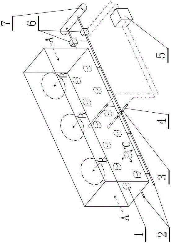
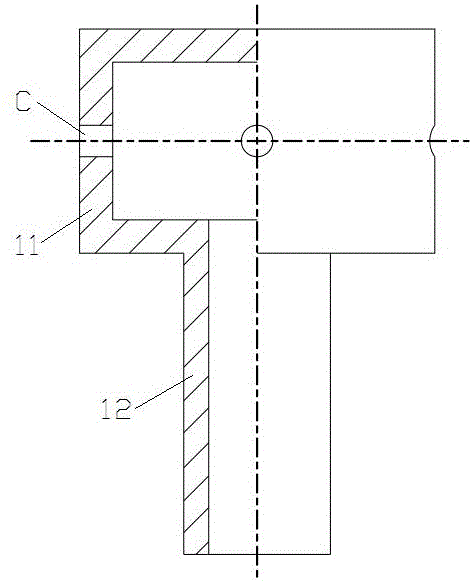
[0023] see Figure 1 to Figure 2 , the soot blowing method for the secondary air chamber of the hedge boiler in this embodiment is: in the middle of the horizontal direction of the secondary air chamber of the hedge boiler, and the first thermocouple 3 is arranged at the bottom position in the vertical direction; There is a second thermocouple 4 arranged in the middle of the air chamber in the horizontal direction and in the middle of the vertical direction; when the secondary air chamber of the hedging boiler is in operation, the secondary air enters the secondary air chamber of the hedging boiler from the secondary air door A, and as the hedging boiler The dust at the bottom of the secondary air...


PUM


Abstract

The invention relates to a soot blowing method and device for flushing a secondary air chamber of a boiler. The characteristics of the soot blowing method of the present invention are: a first thermocouple is arranged in the middle of the horizontal direction of the secondary air chamber of the opposing boiler, and at the bottom of the vertical direction; A second thermocouple is arranged in the middle; a temperature difference is generated between the first thermocouple and the second thermocouple, which triggers the start of soot blowing. The characteristics of the soot blowing device are: it is composed of a wind cap, a compressed gas branch pipe, a compressed gas main pipe, a first thermocouple, a second thermocouple and a PID control module. At least one row of wind caps is arranged along the length direction of the secondary air chamber of the hedge boiler. The air hole on the air cap is exposed to the secondary air chamber of the counterboiler, and the second thermocouple is arranged in the middle of the horizontal direction and the middle of the vertical direction of the secondary air chamber of the counterboiler, and the input terminals of the PID control module are respectively connected with the first thermocouple and the second The thermocouple is connected. The invention can achieve good dust removal effect.

Description

technical field [0001] The invention relates to a method and a device for blowing soot in an air chamber, in particular to a method and a device for blowing soot in a secondary air chamber of a flushing boiler. Background technique [0002] At present, there is a common problem in the hedging boiler, that is, the serious ash accumulation in the secondary air chamber of the hedging boiler. The main reason is: the hot flue gas and the cold secondary air exchange heat and cold in the air preheater, and when the cold secondary air performs heat exchange in the air preheater, the soot in the flue gas is entrained to the flushing boiler In the secondary air chamber, when the unit load is low and the secondary air volume is small, it is easy to cause ash accumulation in the secondary air chamber of the hedging boiler, and with the increase of the ash accumulation, the flow area of ​​the secondary air chamber of the hedging boiler will be damaged. Changes will affect the distributi...

Claims


Application Information

Patent Timeline
Patent Type & Authority Patents(China)
IPC IPC(8): F23J3/00
Inventor 吴桂福薛志鹏陈剑秦鹏廖永浩郝建刚郑文广葛伟吴昱孟繁明
Owner HUADIAN ELECTRIC POWER SCI INST CO LTD
Why Eureka
Try Eureka