High-temperature steam heat pump unit

A heat pump unit, high temperature steam technology, applied in heat pump, steam generation, steam generation method and other directions, can solve the problems of low heating efficiency and poor heating effect, and achieve the effect of prolonging the service life, reducing the temperature of the refrigerant, and realizing the effect of energy saving

Active Publication Date: 2014-10-01
烟台明辉热泵节能科技有限公司
View PDF7 Cites 5 Cited by
  • Summary
  • Abstract
  • Description
  • Claims
  • Application Information

AI Technical Summary

Problems solved by technology

[0003] The invention provides a high-temperature heat pump unit that uses artificial heat sources such as double-stage heat pumps or waste heat to generate boiling water and steam, and solves the technical problems of low heating efficiency and poor heating effect of existing high-temperature heat pump units

Method used


Image

  • High-temperature steam heat pump unit
  • High-temperature steam heat pump unit

Examples


Embodiment 1

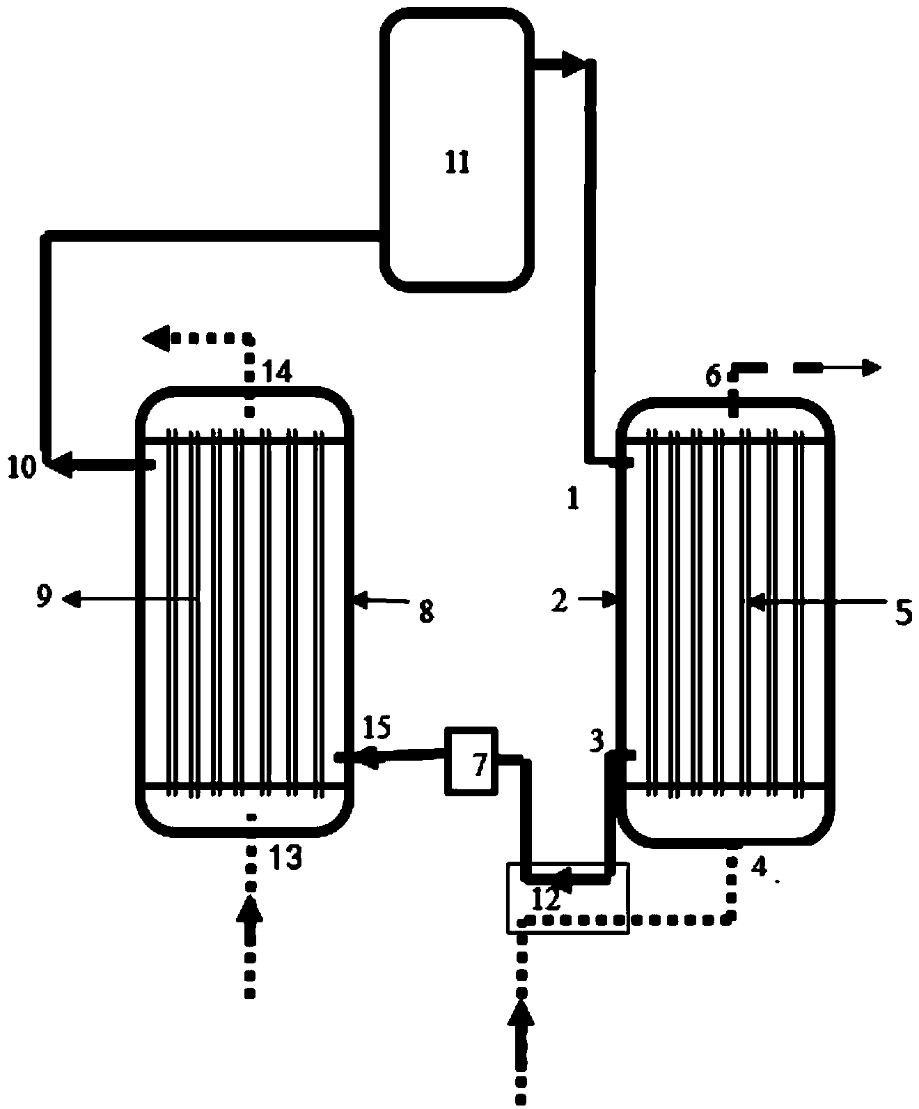
[0024] The high-temperature heat pump unit aimed at recovering waste hot water sources includes an evaporator, a compressor 11, a condenser, and an electronic expansion valve throttling device 7. The refrigerant evaporation outlet 10 of the evaporator is connected to the inlet of the compressor 11, and the outlet of the compressor 11 is connected to the inlet of the compressor 11. The refrigerant condensation inlet 1 of the condenser is communicated, and the refrigerant condensation outlet 3 of the condenser is communicated with the refrigerant evaporation inlet 15 of the evaporator through the electronic expansion valve throttling device 7 .

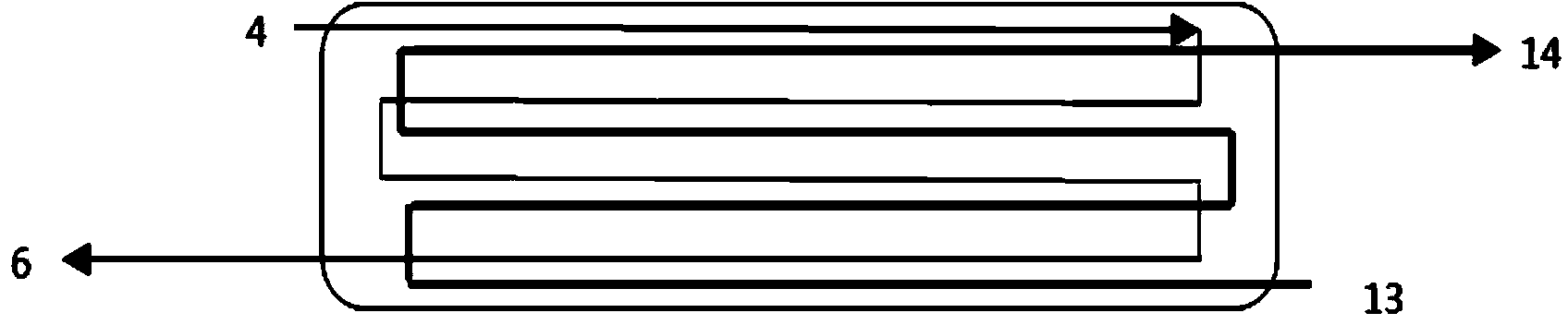
[0025] Such as figure 2 In the right half of the middle, the condenser includes a condensation chamber 2 and a condensed water heat exchange tube 5. There are three chambers in the condensation chamber 2 from top to bottom, which are the first chamber, the second chamber, the third chamber, and the second chamber A plurality of vertica...

Embodiment 2

[0034] For the high-temperature heat pump unit that recovers heat sources such as high-temperature exhaust gas and exhaust steam, a finned evaporator on the market is used, and it is sealed for heat exchange; the structure of the rest is the same as that of the first embodiment.

[0035] In addition, the evaporator adopts the existing horizontal arrangement structure and is used in combination with the condenser in this embodiment to generate waste water and steam, but the efficiency of evaporation and heat exchange is lower than that of Embodiment 1.

[0036] In Embodiment 1 and Embodiment 2, after the generated boiling water vapor is utilized, the remaining waste heat can be recovered and recycled as a part of the waste heat source, which can further improve the efficiency.


PUM


Abstract

The invention provides a high-temperature steam heat pump unit. The invention solves the problems of low heating efficiency and poor heating effect in the conventional high-temperature heat pump units. The high-temperature steam heat pump unit comprises an evaporator, a compressor, a condenser and an electronic expansion valve throttling device, wherein the condenser comprises a condensation cavity and condensed water heat exchange pipes; a first cavity, a second cavity and a second cavity are arranged inside the condensation cavity from the top down; vertical condensed water heat exchange pipes are arranged inside the second cavity; the upper end of each condensed water heat exchange pipe is communicated with the first cavity; the lower end of each condensed water heat exchange pipe is communicated with the third cavity; a refrigerant condensation entrance and a refrigerant condensation exit are positioned on the second cavity; the height of the refrigerant condensation entrance is larger than that of the refrigerant condensation exit; a boiling water / steam outlet is formed in the first cavity; an inlet of water to be heated is formed in the third cavity. According to the invention, ladder temperature produced during the condensation process is fully utilized, so as to produce a high-temperature effect; before water leaves the boiling water / steam outlet, the water is subject to high-temperature heating of an overheating refrigerant and can reach the boiling state.

Description

technical field [0001] The invention relates to a high-temperature steam heat pump unit, which can heat water to boiling and generate steam. Background technique [0002] At present, in order to meet the needs of energy saving and emission reduction, small coal-fired boilers are in urgent need of environmentally friendly alternatives—high-temperature heat pump units. The research direction of high-temperature heat pumps is mainly in two aspects. First, research on high-temperature compressors, such as two-stage and three-stage compression; second, research on new refrigerants; these two technologies, in the traditional structure, whether it is Condenser or evaporator, its refrigerant and water medium flow in and out from the same direction, such as figure 1 , to achieve the heating effect, the water temperature can only be lower than the saturation temperature corresponding to the condensation pressure, and the water temperature can only be raised to around 85°C, the heatin...

Claims


Application Information

Patent Timeline
Patent Type & Authority Applications(China)
IPC IPC(8): F25B30/02F25B27/02F25B39/04F25B39/02F22B1/00
CPCY02A30/274
Inventor 迟永江赵伟
Owner 烟台明辉热泵节能科技有限公司
Why Eureka
Try Eureka