Solar cell and manufacturing method thereof

A technology for solar cells and front electrodes, applied in circuits, photovoltaic power generation, electrical components, etc., can solve problems such as increasing viscosity maintenance time and back electrode layer separation, and achieve the goals of reducing viscosity time, improving bonding strength, and improving deposition rate Effect

Inactive Publication Date: 2016-08-17
LG INNOTEK CO LTD
View PDF4 Cites 0 Cited by
  • Summary
  • Abstract
  • Description
  • Claims
  • Application Information

AI Technical Summary

Problems solved by technology

Therefore, compressive stress may occur between particles, so, the back electrode layer may be separated from the substrate
Meanwhile, if the sputtering power is reduced, the particle size is slightly reduced, so the bond strength between the back electrode layer and the substrate may be enhanced, but the stickiness retention time may be increased

Method used


Image

  • Solar cell and manufacturing method thereof
  • Solar cell and manufacturing method thereof
  • Solar cell and manufacturing method thereof

Examples


Embodiment Construction

[0015] In the description of the embodiments, it will be understood that when a substrate, layer, film or electrode is referred to as being "on" or "under" another substrate, another layer, another film or another electrode, it may be "directly "ground" or "indirectly" on the other substrate, another layer, another film or another electrode, or one or more intervening layers may also be present. Such a position of each component has been described with reference to the drawings. The thickness and size of each component shown in the drawings may be exaggerated, omitted, or schematically shown for the purpose of convenience or clarity. In addition, the size of elements does not utterly reflect an actual size.

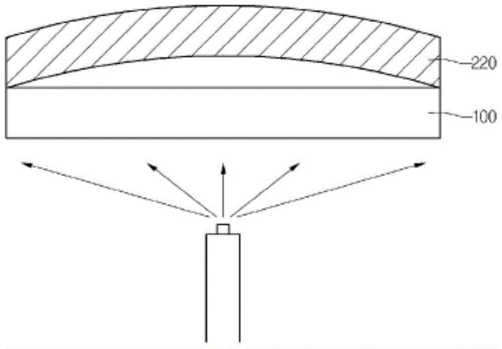
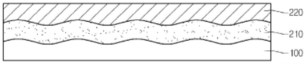
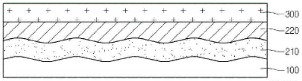
[0016] Figures 1 to 5 is a cross-sectional view illustrating a method of manufacturing a solar cell according to an embodiment. Below, will refer to Figures 1 to 5 A solar cell and a method of manufacturing the same according to the embodiment will be described in det...


PUM


Abstract

A solar cell and a manufacturing method thereof are disclosed. The solar cell includes: a first back electrode layer on a support substrate; a second back electrode layer on the first electrode layer; a light absorbing layer on the second back electrode layer; and, on the The front electrode layer on the light absorbing layer.

Description

technical field [0001] Embodiments relate to solar cells and methods of manufacturing the same. Background technique [0002] A solar cell may be defined as a device for converting light energy into electrical energy by using the photovoltaic effect in which electrons are generated when light is incident on a P-N junction diode. Solar cells can be classified according to materials constituting junction diodes: silicon solar cells; compound semiconductor solar cells, which mainly include group I-III-VI compounds or group III-V compounds; dye-sensitized solar cells; and, organic solar cells Battery. [0003] A solar cell composed of CIGS (CuInGaSe), which is one of group I-III-VI chalcopyrite-based compound semiconductors, exhibits superior light absorption, high photoelectric conversion efficiency using a thinner thickness, and superior electro-optic stability, so CIGS solar cells have attracted attention as a substitute for conventional silicon solar cells. [0004] Gener...

Claims


Application Information

Patent Timeline
Patent Type & Authority Patents(China)
IPC IPC(8): H01L31/0224H01L31/032H01L31/0392H01L31/18
CPCH01L31/022425H01L31/0322H01L31/03923H01L31/18Y02E10/541H01L31/0224H01L31/04H01L31/0236H01L31/02366
Inventor 金钟岘
Owner LG INNOTEK CO LTD
Why Eureka
Try Eureka